It looks really strange, J508 and E202 should have similiar current ~2mA, J505 (E102) - 1 mA, I used Siliconix J508 and J505, LM329 in Erno Borbely voltage regulator's schematics is usually used with 2 mA current. Are you sure that you measured properly (just few minutes ago I tested J508 - 2.2 mA - to be sure) - I mean polarity? If you have 0.7V across D17 - it is or D17 itself or D16 (of course if it is not connected to ground somehow with very low resistance, for example damaged C27), 2SK389 has very high (megaohms) input impedance, if not damaged : if you remove current regulator diode and voltage reference - connect them in serial and apply 15-20V -
if you do not have 6.9V at reference, replace current diode with resistor 4-5K and measure again - if you have 6.9V - this is current diode, if not - voltage reference.
I have all these parts, find what is broken, I can ship you replacement.
if you do not have 6.9V at reference, replace current diode with resistor 4-5K and measure again - if you have 6.9V - this is current diode, if not - voltage reference.
I have all these parts, find what is broken, I can ship you replacement.
Wow what a long tryp, now I have +50Vout regulator going on OK, measured the minus rail and the minus rail damaged: tested all devices, finally was two J505 damaged, one E202 & one J313, now I'm goin to connect to see if I have +-50V both rails
N.B. Of course all voltages measurements with the DVM not damaged") .
.
N.B. Of course all voltages measurements with the DVM not damaged
.
Last edited:
If you have -6V offset with AD820 it means: or AD820 is damaged, or one of its power (+/- 10V, regulated by shunts LM4040) is wrong - I saw few millivolts offset during driver setup after inserting servo opamp. Another issue: how did you connect chassis ground? When I connected it to ground point of driver board I had self-oscillation, I connected ground to chassis only at amplifier input - but I did not use original Borbely PCBs (he already closed his business that time), I designed them myself.
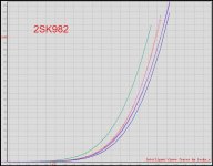
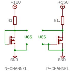
Well managed to measure the K982 & J148 in place Idss I have to measure like mosfets, I guess to input mosfet using 2K2 resistor Transistor matching
I need for the minus rail regulator Q21 K982, Q22 & Q23 both J148
And for the driver minus said Q5 & Q6 both J148
Have VGS
K982 J148
2.69 2.75
2.75 2.76
2.81 2.78
2.83 2.79
2.85 2.82
2.89 2.83
2.91 2.84
2.92 2.85
3.05 x 2 3.03
----- 3.06 x 2
----- 3.08 x 2
----- 3.12
----- 3.16
Wich one to use in each position?
Last edited:
Well managed to measure the K982 & J148 in place Idss I have to measure like mosfets, I guess to input mosfet using 2K2 resistor Transistor matching
I need for the minus rail regulator Q21 K982, Q22 & Q23 both J148
And for the driver minus said Q5 & Q6 both J148
Have VGS
K982 J148
2.69 2.75
2.75 2.76
2.81 2.78
2.83 2.79
2.85 2.82
2.89 2.83
2.91 2.84
2.92 2.85
3.05 x 2 3.03
----- 3.06 x 2
----- 3.08 x 2
----- 3.12
----- 3.16
Wich one to use in each position?
Your J148/K982 are not genuine, VGS is too high.
Attachments
- Status
- This old topic is closed. If you want to reopen this topic, contact a moderator using the "Report Post" button.
- Home
- Amplifiers
- Solid State
- Erno Borbely "Milennium" All Fet Class A Power amp 75W RMS