I have right channel sounding lower than right channel so I measured the driver regulators not giving the +-50V required for 75W and discovered some diodes & fets gone also on the driver, all replaced and now the regulators are working fine. The amp wasn't assembled and adjusted by myself.
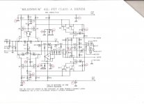
Next step is "adjust the driver DC-wise, by sorting the +Drive, the -Drive togheter and connecting them to the FB point. (The driver is now setup as an independent discrete opamp DC-wise). Connect the +Input to SGND. Apply the supply voltage and adjust the voltage drop across R4 (or R15) with P2. It sould be 3V." "Erno Borbely setup"
I measured more than 3V but can't adjust to 3V with P2. The question is: have I to disconnect +D, -D & FB from the output section power mosfets?
Also is mandatory to mount Q14 in the same output heatsink with the power mosfets, I ask because the person who assembled the amps don't connect any kind of heatsink to Q14?
Attachments
Last edited:
I built this amplifier few years ago - works perfect, but I had opposite problem - the
voltage drop across R4(R15) was less than 3V - due to low IDSS of input JFETs (I used initially BL with IDSS ~7 mA), then I replaced them with V (~12 mA) and everything became OK. If you use 2SK1058/2SJ162 MOSFETs in the output stage - you do not need to mount Q14 to the main heatsink, but if you use 2SJ201/2SK1530 or 2SJ200/2SK1529 - mounting Q14 to the heatsink is mandatory. When you setup driver stage, you have to disconnect D+, D- and FB from output stage and connect them together (like it is wrinnen in Borbely's setup manual).
voltage drop across R4(R15) was less than 3V - due to low IDSS of input JFETs (I used initially BL with IDSS ~7 mA), then I replaced them with V (~12 mA) and everything became OK. If you use 2SK1058/2SJ162 MOSFETs in the output stage - you do not need to mount Q14 to the main heatsink, but if you use 2SJ201/2SK1530 or 2SJ200/2SK1529 - mounting Q14 to the heatsink is mandatory. When you setup driver stage, you have to disconnect D+, D- and FB from output stage and connect them together (like it is wrinnen in Borbely's setup manual).
Last edited:
Thanks for support. You are right, now I read it in the page 3 of manual not needed for 2SK1058/2SJ162 MOSFETs.
The person who assembled the amps mounted 8 caps 47000uF 100V per channel, but manual said two 47000uf 63V or better 100000 63V?
Mine input Jfets Q3,4 & Q5,6 don't have any grade all have as per datasheets Idss 10uA.
If you are refering to Q8,9,10 & Q11,13,14 here I'm using V grade matched.
The person who assembled the amps mounted 8 caps 47000uF 100V per channel, but manual said two 47000uf 63V or better 100000 63V?
Mine input Jfets Q3,4 & Q5,6 don't have any grade all have as per datasheets Idss 10uA.
If you are refering to Q8,9,10 & Q11,13,14 here I'm using V grade matched.
Last edited:
When I talk about input JFETs I meaned Q1(2SK389) and Q2(2SJ109) - these JFETs
I had initially about ~7mA IDSS. Erno Borbely (I wrote him, that time his mail worked) recommended to use V grade or to decrease R8/R9 R11/R12 simultanously - but I prefered to buy V grade JFETs, good matching needed for Q8/Q9 and Q12/Q13 - as they are connected in parallel, and they should have as high IDSS as possible (I selected
about 16.5 mA). I used RIFA PEH200 100000uF x 80V capacitors - you can read setup
manual - as much as you can!!! And, my own opinion - I prefer to use single capacitor
per rail - I can not explain, but on my taste the sound is better (I also tried Kendeil 47000 x63V x2 in parallel per rail at the beginning - but, the final is one 100000 per rail. I posted the pictures of my amp:
https://www.diyaudio.com/forums/solid-state/96192-post-solid-pics-484.html#post4838733
Dear Felipe,
You are right, you have to measure "0" at connection point of D-, D+ and FB, one probe to this point(D-,D+, FB), second - to ground, do not forget to remove servo chip (AD743 or AD820) from dip-8 socket, I did setup of 3V and 0 few times, as setting up of "0" slightly changes 3V drop - but in two-three iterations you should get perfect result. Then restore D-, D+ and FB connections (to the output stage), put servo op amp to it's place and set bias (1.76 A, as I remember) - give the amplifier to work half an hour and correct bias again - it should became a little bit lower
with time. That is the whole setup, if you do not need balance input.
Best regards,
Alex
Last edited:
Thank you Alex. Measures 0V but when I turn the P3 can't increase or decrease the 0V, can be the P3 trimpot damaged?
Yes bias 1.76A for 50W class A, mine 2.15A for 75W class A.
The bias is across 50 or 75W/8 Ohm dummy load?
How can increase/decrease the bias point?
Yes bias 1.76A for 50W class A, mine 2.15A for 75W class A.
The bias is across 50 or 75W/8 Ohm dummy load?
How can increase/decrease the bias point?
Last edited:
Dear Felipe,
It looks like you have something damaged in the input stage, maybe P3 - I built few Borbely amplifiers with similiar topology, and always it was easy to set "0" (and 3V, as a minimum changing of P2 position caused significant changes of voltage drop on R4/R15 i.e input stage current)- maybe you forgot to remove servo op amp from its socket (with op amp connected changing of P3 does not work - servo compensates your adjustment, and you always have value close
to 0 at the output). To set bias - use P4, I did not put any load when I set bias (theoretically, if you have 0 at output, current through the load should be 0, practically you have few tens of millivolts - currect is close to 0). And, do not forget to short input to (signal) ground when you perform DC setup.
Best regards,
Alex
If you look at schematic, you can see that it is symmetrical, resistors R8, R9 - 100 Ohm,
R11, R12 - 75 Ohm, P3 - 50 Ohm, so R8 + R9 = 200 Ohm, R11 + P3 + R12 - also = 200 Ohm, you cat put 200 Ohm pot instead of 50 Ohm (P3) and short R11 and R12, or, as I offer, put 100 Ohm instead of P3 and replace R11 and R12 with 50 Ohm (closest 49.9 Ohm) resistors - it will keep symmetry. If you put 25 Ohm instead of 50 Ohm trimmer,
you should use R11, R12 value 175 / 2 = 87,5R (closest 86.6 Ohm), in my amp the P3 is almost in the center, so I think 25 ohm will be enough - I selected all components very carefully with curve tracer - but I do not know about yours.
For a better precision, you can put the pot in parallel of a resistance that bot give the original pot value required.
That's a good idea, I will try P3 trimpot 100 ohms + parallel 100 ohm fixed resistor.
If you look at schematic, you can see that it is symmetrical, resistors R8, R9 - 100 Ohm,
R11, R12 - 75 Ohm, P3 - 50 Ohm, so R8 + R9 = 200 Ohm, R11 + P3 + R12 - also = 200 Ohm, you cat put 200 Ohm pot instead of 50 Ohm (P3) and short R11 and R12, or, as I offer, put 100 Ohm instead of P3 and replace R11 and R12 with 50 Ohm (closest 49.9 Ohm) resistors - it will keep symmetry. If you put 25 Ohm instead of 50 Ohm trimmer,
you should use R11, R12 value 175 / 2 = 87,5R (closest 86.6 Ohm), in my amp the P3 is almost in the center, so I think 25 ohm will be enough - I selected all components very carefully with curve tracer - but I do not know about yours.
If Osvaldo idea doesn't work I will try P3 200 ohm shorting R11 R12.
Thanks for support guys.
Good night
Felip
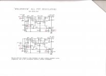
I have problems now with the regulator, in the plus side I'm measuring -5Vout, the regulator input is OK +55V but when I measure voltage across D17 is 0V in place 6.9-7V, I desoldered the voltage reference diode from the PCB and measured with DC75 and says is OK
The measuring is done connecting both rails positive and negative (+Vs2 & -Vs2) to the driver, SGND to PGND (Driver) and PGND from PSU PCB to PGND (Driver) so only disconnected from output section: FB, +D & D-
I guess wasn't necessary to connect the output section to the driver?
I desoldered all diodes & FETS of the plus side of regulator and all the devices are OK. Can be P5 damaged?
Attachments
Last edited:
For a better precision, you can put the pot in parallel of a resistance that bot give the original pot value required.
Done paralleled the pot with a 100 ohm but I have now problems setting the regulator to +50V
Is it possible that D16 is damaged - this is current regulator diode (J508 2 mA). You can remove it from the board and easily check - connect milliampermeter in serial with it and apply ~10V - (of course take care about diode polarity) - milliampermeter should show 2-2.5 mA, if not - the diode is damaged. If you do not have spare one, it is possible to replace it with ~22K resistor, but in this case you should connect electrolytic capacitor 22-47 uF in parallel to C27 to protect voltage reference (LM329) at start point - I offer to to it only fo test, you still need to find J508, if it is damaged.
- Status
- This old topic is closed. If you want to reopen this topic, contact a moderator using the "Report Post" button.
- Home
- Amplifiers
- Solid State
- Erno Borbely "Milennium" All Fet Class A Power amp 75W RMS