The attachement on page 13 illustrates the use of an inductor to reduce inrush currents.
https://web.wpi.edu/Pubs/E-project/...icted/Inrush_Transient_Current_Mitigation.pdf
https://web.wpi.edu/Pubs/E-project/...icted/Inrush_Transient_Current_Mitigation.pdf
I guess the only problem is that 2 Ohms sounds kind of high for a power amp...
What I would up doing myself, was to abandon design-using-datasheets and instead perform design-by-lab-experiments. The datasheets were not in a single standard format and they were driving me crazy.
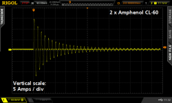
I purchased a bunch of different Inrush Current Limiters, connect them to my amplifier, and measured three pieces of data for each ICL: (1) DC output voltage of power supply under full load {easy to do with a class A amp!}; (2) temperature of ICL device exterior; (3) peak inrush current at switch-on. See attachment 2 of post #17 in linked thread.
What mattered to me was where the rubber met the road: DC output. Rather than getting worried about too much or too little resistance in the primary circuit, I just measured the final result. I figured that if an ICL device had too much resistance, it would sag the primary, which would sag the secondary, which would decrease DC Vout. Therefore: just measure DC Vout.
Once I had the table of measured data for all the ICLs, I picked the one that represented the best compromise between inrush current and DC output voltage. ICLs that gave extremely low inrush current, had lower DC output voltage. ICLs that had nice high DC output voltage, also had high inrush current. So, use your gutt instinct to choose an acceptable tradeoff.
Measuring inrush current repeatably, so that every switch-on event in every experiment occurs at exactly the same phase of the incoming mains waveform, took some doing. I built a little mains synchronized switch, see post #41. Notice the adorable feces-rig with battery and masking tape.
_
Attachments
Last edited:
I use two 10R/7.5A NTC ICL in series in my power controller. They are engaged for 200ms at power ON/OFF.
Ka1 - AC Power Controller - Google Photos
Ka1 - AC Power Controller - Google Photos
Those made so far are valid and concrete indications.
Personally with commercial and self-made amplifiers, with power transformers over 400/500 VA and that occasionally had this annoying problem of the DC component on the power supply, that sometimes came to be heard even on the speakers, I solved at the root with a cheap DC-Blocker - Main DC Filter, that I use and keep jealously.
Personally with commercial and self-made amplifiers, with power transformers over 400/500 VA and that occasionally had this annoying problem of the DC component on the power supply, that sometimes came to be heard even on the speakers, I solved at the root with a cheap DC-Blocker - Main DC Filter, that I use and keep jealously.
Thermistors on a class A amp make sense since the load is well defined.
I am getting my transformers wound by a small outfit near where I live. The transformers are oversized and run at about 15-20% lower flux density than transformers you would typically buy off one of the big suppliers. The cores are 'stabilized' as well. Normally the iron core is wound from a long strip if mag steel and then enclosed in a plastic housing. On a stabilized core, they inject and varnish vacuum impregnate the strip wound core inside the plastic shroud so mechanically they are very, very quiet.
The commercial cores I have are nowhere near good enough for audio work - they all hum, rattle and buzz with DC on the mains and I suspect because some of them are additionally saturating.
Last edited:
... or use a AC mains DC blocker like this one here 2stageEF high performance class AB power amp / 200W8R / 400W4R
Schematic and simulations a few posts before.
BR, Toni
Schematic and simulations a few posts before.
BR, Toni
Bonsai, I don't think too many DIYers encounter core saturation, because the mentality "If some is good then more is better" often leads hobbyists to purchase a 400VA transformer for an amp that draws 150 watts from the mains. There are many many homebuilt clones of First Watt amplifiers (2 x 25W RMS output, class A) with 400VA Antek or Toroidy transformers inside. After all the price difference between a 200VA toroid and a 400VA toroid is only $21. But the bigger one is twice as good, right?
Its not the load that saturates the core Mark - to adjust the core magnetization you adjust the number of turns (you know that anyway). Even on a 400VA commercial core you are likely to get noise problems unfortunately and I've learnt over the years that good transformers cost.
I think the problem is most of the commercial stuff is spec'd at say 30 deg or 40 deg transformer temp rise and to reduce costs they use a small core and run the flux density close to maximum.
The guy that winds my stuff demo'd it to me - amazing what a few turns on the primary do for noise and flux density.
Smaller transformers with higher primary resistance are less likely to buzz - its the bigger ones with low DC primary resistance that suffer from DC on the mains problems because the primary current can get very high on the offset side.

I suppose US buyers of dual-voltage transformers with two primaries, have the option of cutting the magnetization in half (to get a big margin of safety against core saturation) through brute force: Don't connect the primaries in parallel. Connect the mains to one primary and don't use the other primary at all; just terminate it with something harmless like a 22K 1W resistor. You've reduced magnetization by 2X, which of course cuts the VA rating in half too. But the additional cost of a doubled-VA transformer is not huge; for example the delta is $21 when going from 200VA to 400VA.
I may be thinking about this wrong, but I'm not sure your suggestion would help so much...It would increase the DCR, which moves in the direction of limiting peak currents. If a few ohms of Input current surge limiting stops the buzz, then this should also help...Maybe that's the effect you're pointing to...and in that case, I'd have to agree.
Still, the apparent inductance wouldn't change, since both primary windings are tightly coupled, so the magnetizing current (dominated by the inductance) really wouldn't change so much...
It might be a game of inches...where a few Ohms is enough....but I thought it worthwhile to split this particular hair...
comments invited....
The formula for flux density is
Bm = E/(4.44*f*N*A)
where
Bm = Max flux density in Tesla
E = RMS input voltage
F = Frequency in Hz
N = # of turns
A = is the core cross sectional area in metres^2
For a typical commercial mains transformer, the flux density is run at 1.8 Tesla.
So, if you increase the turns, the flux density goes down (but the copper losses go UP).
If you want real low flux density, you could wire the two 110 VAC primaries in series but specify the secondary voltage for double the voltage you actually require.
Disclaimer: I have NOT tried this.
Separately, you can see why commercial suppliers reduce the windings and run transformers at the max flux density - you minimize copper losses, amount of copper used and utilize fully the available area of the core. However, not too good for high quality audio of course.
Last edited:
- Status
- This old topic is closed. If you want to reopen this topic, contact a moderator using the "Report Post" button.
- Home
- Amplifiers
- Solid State
- Is inrush current limiter responsible for quieter power transformer?