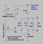
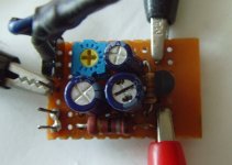
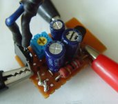
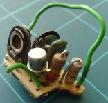
A tiny amplifier using one small signal transistor. It is capable of driving a speaker directly and fits on a 25x20mm protoboard.
The amplifier operates in class-A from a 5V supply at 110-120mA quiescent current. Input is at soundcard line level. Output power is estimated to max 150mW into 8 ohms. Power consumption 0,6W.
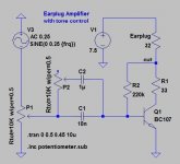
Component values are selected through simulation and experimentation. A voltage of around 2 volts at the collector and an output voltage of 4V works well.
R1 runs a bit hot and should be rated 1 W.
R2 may need to be adjusted for a collector voltage of around 2V and 110-120mA current.
C2 and C3 can be combined into a single larger capacitor.
Q1 is MPS2222A and not 2n2222A as on the diagram. Selected because gave the best result between the tested ones. I assume that BC337, 2N2222 and similar will work well too.
U2 is can be replaced by a fixed resistor divider or even omitted.
This is probably one of the simplest amps you can build, it works well enough for an internal PC speaker. It is not exactly HiFi, but makes a lot of noise when connected to a JBL mini monitor")
The amplifier operates in class-A from a 5V supply at 110-120mA quiescent current. Input is at soundcard line level. Output power is estimated to max 150mW into 8 ohms. Power consumption 0,6W.
Component values are selected through simulation and experimentation. A voltage of around 2 volts at the collector and an output voltage of 4V works well.
R1 runs a bit hot and should be rated 1 W.
R2 may need to be adjusted for a collector voltage of around 2V and 110-120mA current.
C2 and C3 can be combined into a single larger capacitor.
Q1 is MPS2222A and not 2n2222A as on the diagram. Selected because gave the best result between the tested ones. I assume that BC337, 2N2222 and similar will work well too.
U2 is can be replaced by a fixed resistor divider or even omitted.
This is probably one of the simplest amps you can build, it works well enough for an internal PC speaker. It is not exactly HiFi, but makes a lot of noise when connected to a JBL mini monitor
Attachments
"Simpler?"There are numerous examples on you tube of simpler circuit using IRFZ44 .
YouTube
Are you joking?
You are not showing an Amplifier (which has gain and can be driven by a small signal, such as the typical 100mV RMS available from a phone) but a unity gain buffer, which needs in this case 3Vpp
to be fully driven.And in general about full rail to rail (or rail to ground) drive signal swing.
Don´t compare apples to oranges
@kokoriantz
Yes, there are many nice schematics out there. The one you refer to is a simple source follower circuit and has no voltage amplification. It works well if your input voltage is high enough. But is not suitable if you want to boost a weak line signal to power output level....
@JMFahey
I think we can agree on that.
Pulling DC power through a speaker is rude. It drives the voice-coil off the center of the magnetic gap, reducing useful excursion (though may still be ample for the power). It creates useless heat in the coil (here, not a lot).
Tying one side of the speaker to an off-ground power supply is rude. If it wasn't 5V it would be a shock hazard. As it is, a short to ground wants to burn-up the power supply (though assuming USB-wart, maybe no smoke).
The circuit is not unity gain, as someone asserted (look again). An optimistic analysis suggests gain of 36. The input impedance tends to be around 33 Ohms, so ANY parasitic resistance matters a lot. It may drive fine from an iPod etc.
R1 C23 simply waste-off 2V of the 5V supply, do no other good. A couple D-cells would power this a long time. Or it could be correctly re-designed to use all the 5V available, make 2.7 times the power.
The power output is easily estimated. The speaker idles with 1V across it. This can go to zero but no further. Assuming the transistor is happy passing 250mA (the parts mentioned are marginal), then we can pull another 1V peak. 2V peak-to-peak is 0.707V RMS. (0.7^2)/8 is 0.062 Watts.
THD at this level will be gross, >20%. It will be a third, 7% mostly 2nd, at 1/3rd the voltage, 1/10th the output, 6mW. Draw the line anywhere between 6mW and 60mW, depending on the THD you will tolerate. Several % THD at several milliWatts is not real offensive.
If you want more power with minimum parts, you can use a TO126 darlington (these usually come with integrated b-e resistors, so you can bias them with a single c-b resistor) like a BD675. That would make it a one trimpot, one cap, one resistor, one transistor rude-boy amp - "louder than yours", haha.
The original Earplug Amplifier
Thank you for comments!
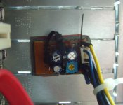
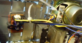
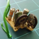
Here is the almost 40 years old earplug amplifier that inspired the current build. The design came from an electronics magazine and it was installed in a battery powered Philips cassette player which didn't come with an output jack. It was squeezed into an empty spot just above the main pcb. This design only draws power when the earplug is connected. P1 sets the level, P2 is the tone control.
It worked well for its purpose and when the cassette player was discarded I salvaged the amp since this is one of my earliest projects.
Thank you for comments!
Here is the almost 40 years old earplug amplifier that inspired the current build. The design came from an electronics magazine and it was installed in a battery powered Philips cassette player which didn't come with an output jack. It was squeezed into an empty spot just above the main pcb. This design only draws power when the earplug is connected. P1 sets the level, P2 is the tone control.
It worked well for its purpose and when the cassette player was discarded I salvaged the amp since this is one of my earliest projects.
Attachments
What do you call this?The circuit is not unity gain, as someone asserted (look again
>SimpleAmp.gif<
* Drain straight to +V
* Signal OUT: Source to ground through load
* Signal IN: to gate.
Attachments
Now for the comments:
@PRR
Yes, it's rude to send DC through a speaker element and to pull the voice coil off center. But for some reason it actually sounds louder compared to a traditional setup with output capacitor. Also the speaker could have been connected to ground, this would be possible with mirrored setup and a PNP transistor instead of NPN.
The voltage gain is estimated to 15~20x and the harmonics are bad as you predict. Maybe an emitter resistor of 1-2 ohms would help?
From simulation it seems to be hard to squeeze more than 0.8V peak (1.6 Vpp) out of this contraption without lowering R1 and increasing the bias with the risk of frying the transistor and maybe the speaker too.
The capacitors across R1 pass the full voltage swing at the collector on to the speaker and actually increase power without increasing the quiescent current. Look at them as output capacitors.
@anti
You are right, a darlington would work much better, an output voltage swing of 2.2~2.4Vpp should be possible. But it will run much hotter and the idling current may become to much for the speaker. Then we actually have a 2-transistor amp including 2 more (built-in) resistors..... It would be worth trying anyway.
----
I didn't bother to scope the circuit yet, but will do one day. It could be nice to see the waveforms and clippig voltage. But it is already built in, so I may need make a replica in order to do further analysis.
After all this is Flea Power for PC and similar use, but it may be scaled up to a couple of watts.
@PRR
Yes, it's rude to send DC through a speaker element and to pull the voice coil off center. But for some reason it actually sounds louder compared to a traditional setup with output capacitor. Also the speaker could have been connected to ground, this would be possible with mirrored setup and a PNP transistor instead of NPN.
The voltage gain is estimated to 15~20x and the harmonics are bad as you predict. Maybe an emitter resistor of 1-2 ohms would help?
From simulation it seems to be hard to squeeze more than 0.8V peak (1.6 Vpp) out of this contraption without lowering R1 and increasing the bias with the risk of frying the transistor and maybe the speaker too.
The capacitors across R1 pass the full voltage swing at the collector on to the speaker and actually increase power without increasing the quiescent current. Look at them as output capacitors.
@anti
You are right, a darlington would work much better, an output voltage swing of 2.2~2.4Vpp should be possible. But it will run much hotter and the idling current may become to much for the speaker. Then we actually have a 2-transistor amp including 2 more (built-in) resistors.....
It would be worth trying anyway.----
I didn't bother to scope the circuit yet, but will do one day. It could be nice to see the waveforms and clippig voltage. But it is already built in, so I may need make a replica in order to do further analysis.
After all this is Flea Power for PC and similar use, but it may be scaled up to a couple of watts.
You can use smd components with a to126 build and make it really compact, so you can screw-mount the complete board to the enclosure (with to126 plastic side to the enclosure, it will cool it down enough, no insulation needed). You can also add a emitter degeneration resistor. It will still be smaller and louder than what you have now. Maybe even cleaner sounding, even if you use tantalum or ceramic caps for signal coupling.
...the speaker could have been connected to ground, this would be possible with mirrored setup and a PNP transistor instead of NPN.
That would move the INput to reference the supply rail.
....hard to squeeze more than 0.8V peak (1.6 Vpp) out of this contraption without lowering R1 and increasing the bias with the risk of frying the transistor and maybe the speaker too...... it may be scaled up to a couple of watts.
Given BIG transistor and BIG loudspeaker, it may be scaled quite huge. An old E-V EVM-15B stage-amp speaker can stand 50 Watts of DC heat, so run a 40V supply, 2.5 Amps of DC in the voice coil, get over 20 Watts of "audio" at many-% THD. Bass will be severely restricted because the voice coil will be several mm off its design center. But hey, just one transistor! (On a motorcycle-head heatsink.)
That is NOT what was posted this thread #1. I don't know where it came from.
My post #3 was answering post #2 exactly above.
Not only it was the one before mine, I even **quoted** it.
Quote:
Originally Posted by kokoriantz View Post
There are numerous examples on you tube of simpler circuit using IRFZ44 .
YouTube
Not sure why you mention post#1 when I was clearly referring to the circuit shown in #2
So much so, that I even screencaptured and posted the relevant frame showing the circuit in all its glory.
Oh... One more thing that I am just complettely clueless about: does a speaker coil actually swing above the power rail (like a proper choke would) or is it just too "damped" with the membrane to actually do so?
Hypothetically (perhaps I'm totally wrong here) that would allow such a simple circuit to bias closer to the supply rail, off-center, so reducing the idle dissipation a bit.
Hypothetically (perhaps I'm totally wrong here) that would allow such a simple circuit to bias closer to the supply rail, off-center, so reducing the idle dissipation a bit.
> does a speaker coil actually swing above the power rail
Certainly not in the middle of the speaker's range, the main impedance minimum, say 150Hz-600Hz (depending a lot on the speaker). Since this is typically where the bulk of music Power lays, that's What Matters.
I dare-say it can swing over the rail at bass resonance, and maybe in the top octaves. However only if the amplifier is giving "no" damping. Since most hi-fi speakers are designed for heavy damping, this would be "bad".
I kind of supposed something like that would be the case - but honestly I had no clue if that would be true. However, most small-dia small-power fullrange speakers seem to have the bass resonance in 120-180Hz or thereabouts) region, and that may affect the outcome of such a simple amp.
(I was briefly thinking what would happen if paraffeeding another small speaker via a cap from the collector).
(I was briefly thinking what would happen if paraffeeding another small speaker via a cap from the collector).
- Status
- This old topic is closed. If you want to reopen this topic, contact a moderator using the "Report Post" button.
- Home
- Amplifiers
- Solid State
- Flea Power Amplifier