
Most of the parts easy to get hold of. Less common parts are the style of phono socket used on the input board as well as the heatsinks for the voltage regulators. On the PSU board I had to get the Songle relay and the barrier blocks from China via ebay. This is from the UK, may be easier from elsewhere.
I got schematics, BOM, and pcb layouts for each board plus setup instructions and latest parts revisions. Also got drilling templates for the heatsink and back panel for the input board. As Amplitude says the boards are thick and well made. You don't get an exact Bryston clone - very close but not exact. Some small plusses and some small minuses. I must admit too that I haven't stuck exactly to the BOM. For instance I used 100uF bipolars for C4 (input) and C5 (feedback), instead of 68uF elcos, in the interests of distortion reduction. This highlights one of the small differences between the original and the clone - the Bryston has a dc coupled input whereas the clone has and ac coupled input via C4.
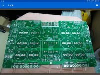
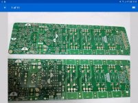
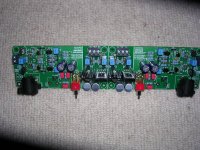
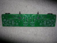
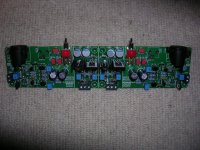
Here's some photographs of my input stage build. Its complete except for the phono sockets, which are en route from China. As you can see I'm not the worlds greatest photgrapher but there's enough detail to see whats involved
Attachments
Looks great chalky, yes the rca is not the easiest part to find, I was considering moving the input connectors of pcb, I read some reviews of original Bryston, peoplo complained about the rca connectors because they could break.
Sat for 15 minutes with output board, seems that if I lift one leg of each constant current diode, the voltage drop over r24 r60 is within spec, am puzzled as to why, need more time and more coffe.
Keep up the good work chalky, the pics aren't as bad as you say
Sat for 15 minutes with output board, seems that if I lift one leg of each constant current diode, the voltage drop over r24 r60 is within spec, am puzzled as to why, need more time and more coffe.
Keep up the good work chalky, the pics aren't as bad as you say

Differences between Bryston 4bsst input stages and clone:-
1) The input amplifier of the Bryston has switch selectable gain of 1.5 or 2 whilst the clone has a fixed gain of 3.
2) The clone has back to back diodes across the inverting and non-inverting of the input amplifier whereas the Bryston does not.
3) The input of the Bryston is dc connected but the clone uses a 68uF electrolytic capacitor
4) Signal ground is connected to chassis ground via a paralled 100nF capacitor and 220R resistor on the clone; whereas the Bryston connects the star ground to the chassis ground via a paralled 100nF capacitor and 100R resistor bridged by two series connected pairs of back to back diodes ( implemented by a suitably connected 35A bridge rectifier).
5) The clone has no guidance on how to deal with pin 1 on the xlr connector. In particular some xlr sockets have (removeable) strap between pin 1 and one of the chassis mounting holes ( connects pin 1 to metal chassis when you insert metal screw) and some do not. Those that do will short out the 100nF capacitor and 220R resistor mentioned in 4)
6) The +/- 33v supplies to the input amps are obtained slightly differently in each case.
There are probably other differences that I haven’t spotted yet.
Probably not. The ebay seller doesn't publish the schematic but emails the details when you buy the pcbs. However Bryston publish the schematics of their amps here Technical Documents - Bryston so youcan easily find the 4B SST. The "clone" we're talking about is very similar to the real thing.
Finally got back to work on my 4bsst klone - got interrupted by a nasty bout of genuine influenza. I finished the input board and everything tested fine. There's a small gotcha if you test the input board by itself - the signal ground and the stabilised power supply ground are not connected on the pcb. So if you, like me, use a floating power supply as input to the pcb stabilised power supply then there is no common ground and the input board does not work. A temporary wire bridge fixes this. The overall gain of the input board from the phono input is x2 not x3 a I previously stated.
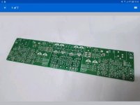
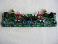
The discrete component opamp has a gain of x3 but there is x0.667 attenuation at the input so overall the gain is x2. The real Brystons have their phono input sockets attached to the pcb and not the metalwork, so there is a point of weakness. The klone phono sockets are soldered to the pcb but also have mounting nuts to fix them to the back panel, so no weakness there. You can see this in the attached photograph. I ran a quick fft spectrum analysis with the input board producing a 1v rms output at 1kHz and any distortion was lost in the noise. I probably could have dug distortion out of the noise if I averaged for long enough but with a figure of well under -100dB I wasn't inclined to bother.
As well as documenting my build of the Bryston 4bsst klone I intend to redesign both the input board and the power amp board. The power supply and protection board will remain unchanged. Why bother to do this when I'm sure the klone will measure and sound fine? Well the input board and the input/vas of the power amp board use a common discrete component symmetrical opamp design which performs fine, but can definitely be improved. The opamp has npn and pnp input long tailed pairs and the collector currents of neither pair perfectly balanced - close, but far enough apart to give rise to small extra distortions.
The choice of push pull vas transistors in the power amp is sub optimal and suitable replacements will yield further small reductions in distortion, particularly at hf. The thermal tracking of the Vbe multiplier needs some investigation ( it may be ok ) and the circuitry around the quiescent current setting potentiometer needs to be put back to something resembling the Bryston original. Otherwise its far too easy to blow up the output devices unless the pot is set correctly before switch on. I'll redraw the original discrete component opamp circuit and aslo sketch out some alternatives. For the moment I intend to leave the output stage of the power amp as it is.
Attachments
- Home
- Amplifiers
- Solid State
- Bryston 4B SST clone