They might work, but the bryston is made with " slow" transistors mjl21193/94 are 4mhz the mentioned are 30 mhz, you might end up with a high power oscillator, but nothing some pf bypass caps couldn't handle.
Between gate and earth?
I think something like 100pf in series with 100R between gate and drain would be a good place to start. With mosfets you can also slip a ferrite bead on the gate lead in lieu of or as well as a gate stopper resistor. Some people don't like ferrite beads but they work for me. Thing is if you're going to use different parts you need to be prepared to experiment - preferably using a power supply with an adjustable current limit.
You could also start with lower value, say 33pf, se its stable , if not increase, and yes beads work, I had trouble with greg ball ska amp, and they helped.
You should aim for lowest value possible
when you said stable you mean not distortion?
With stable I mean , no oscillation, lower value capacitor means better hf performance, and as chalky said it has to be a rc.when you said stable you mean not distortion?
More progress. I've attached a photo of my nearly completed power supply and protection board. I'm going to fix heatsinks to the bridge rectifiers, and make up a couple of solid state relay pcbs to replace the loudspeaker protection relays. I'll make them with the same footprint and connections as the mechanical relays so that they are a drop in replacement on the main pcb. Initially I'll make them up on small pieces of perfboard and then later on I'll do proper pcbs.
Why you didn’t use a 10000uF like the diagram?
After lots of hours matching pn100a and pn200a one channel is fully assembled and 100% stabil, put signal generator on and it produces near perfect square and since wave. Can't wait to get heatsink drilled and push it more,
Why dos you Put caps near the power transistor. In diagrama circuit doesnt exist. ?
Hi..
The extra capacitance is because of the amp chassis history, at first it was a proto type for a Danish high end brand, it shorted a lot of to3, and I doomed it dead, then it became a blameless by a guy here named Carlos (destroyer dx), well then the itch started and it became the bryston, so extra caps always been in chassis, total capacitance is 114000uf per rail.
Is there a company that can make rear plate costumized, preferably not to expensive?
Pic is of the original amp.
What si the effect of extra uF? Dont you have a current peak at on?
The capacitors close to transistors are not shown in schematics but they act as rail capacitors just really close to were power is needed, if they have a effect I don't know, but I guess because of their proximity that power in available at demand, they are optional.
As to all the uf, well its diy and we can do what we want, but yes it is overkill, and does need a soft start so not to replace fuses all the time.
As to all the uf, well its diy and we can do what we want, but yes it is overkill, and does need a soft start so not to replace fuses all the time.
josejuancano.
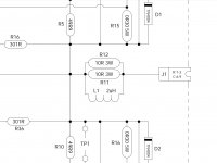
Coil is 2uh use a online calculator and do the math.
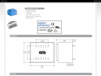
As to the small 12 volt transformer, I think it is a core el48 , but measure the pcb holes and find a suitable transformer, pcb accommodates different sizes, I used a old one I had, needed some leg bending but works fine
Coil is 2uh use a online calculator and do the math.
As to the small 12 volt transformer, I think it is a core el48 , but measure the pcb holes and find a suitable transformer, pcb accommodates different sizes, I used a old one I had, needed some leg bending but works fine
Attachments
Here's some photographs of my input stage build. Its complete except for the phono sockets, which are en route from China. As you can see I'm not the worlds greatest photgrapher but there's enough detail to see whats involved
Is it possible to change the feedback divider and not use the input module?
I would guess so; but remember that if you increase the gain you'll also increase the distortion. The upside is that you'll increase the stability. Doubling the gain might be a good compromise.
I look at the scheme 12.01.88. Divider 1k and 33k, the gain is standard for UM, 29-33db.
Not sure we're talking about the same thing here. The 4B SST power amplifier has a gain of about 14 and the separate input module has a gain of 2, single ended. The gain of the power amp by itself is a bit low without an input module. If you want to dispense with the input module you can increase the power amp gain to 20-30 by altering the feedback resistors. I'm not sure which schematic you're referring to.
Not sure we're talking about the same thing here. The 4B SST power amplifier has a gain of about 14 and the separate input module has a gain of 2, single ended. The gain of the power amp by itself is a bit low without an input module. If you want to dispense with the input module you can increase the power amp gain to 20-30 by altering the feedback resistors. I'm not sure which schematic you're referring to.
Chalky, We speak the same way. In case of poor quality of the input module, you can try changing the divider to gain 29. I am not responsible for the originality of the file.
I can’t attach, size is invalid.

Last edited:
- Home
- Amplifiers
- Solid State
- Bryston 4B SST clone