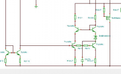
btw: the main mods I made to that doa are:
- dual trannies ccs
- degen res on ltp legs
- improved current mirrors
- much higher bias on vas and output, for really hard class-A all the way.
Surely it would run warm, so heat-sinking the outputs should be done. Nearly half a watt to dissipate from each output.
And the vas trannies would also get warm, with something like 160-170mW each to put out, but likely ok as is, or a small heatsink could also be added to those, a to92, feasible.
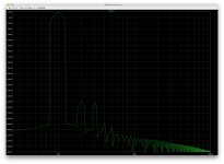
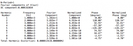
Sim results are more than excellent. Remains to be seen if a real one can be built that approaches this.
- dual trannies ccs
- degen res on ltp legs
- improved current mirrors
- much higher bias on vas and output, for really hard class-A all the way.
Surely it would run warm, so heat-sinking the outputs should be done. Nearly half a watt to dissipate from each output.
And the vas trannies would also get warm, with something like 160-170mW each to put out, but likely ok as is, or a small heatsink could also be added to those, a to92, feasible.
Sim results are more than excellent. Remains to be seen if a real one can be built that approaches this.
A few more details about the improved doa with mirrors.
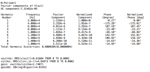
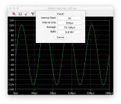
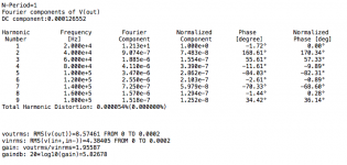
Since that sim is set up to give it a gain of about 2 (6db), I ran it with a 6V (peak) input, to use that as an arbitrary reference to get a reading for SNR.
We get about 128db SNR at that level of reference, but that would go up if we looked for more, which it can definitely do, with plenty of headroom left, even with the supply rails still at 28V.
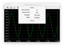
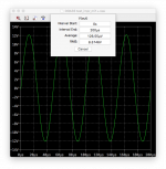
Output was about 12V peak (~9Vrms), on 600ohms. We're not even half way up to rail voltage.
Class A is nice
Since that sim is set up to give it a gain of about 2 (6db), I ran it with a 6V (peak) input, to use that as an arbitrary reference to get a reading for SNR.
We get about 128db SNR at that level of reference, but that would go up if we looked for more, which it can definitely do, with plenty of headroom left, even with the supply rails still at 28V.
Output was about 12V peak (~9Vrms), on 600ohms. We're not even half way up to rail voltage.
Class A is nice
Attachments
Yeh excellent performance of the sim Spookydd. Not sure how it would do in real life however because there's nothing to explicitly set the vas current. You'd probably need to add the resistors across the mirror collectors and use a Darlington vas as Bob Cordell does ( p206 in his Designing Audio Power Amplifiers book ). He used this scheme for the DH220 redesign as discussed in the thread on this forum. I prefer the Glenn Kleinschmidt, Giovanni Stochino, Sansui, or even the Self approach as it gives much tighter control over the vas current.
Not sure how it would do in real life however because there's nothing to explicitly set the vas current.
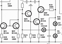
Well, if you're wary of doing it this way, how about that example attached?
Had to adjust a few things to accommodate it, but inserting a common collector in the vas should fix that issue of uncertainty.
However the thd result isn't quite as stellar, but still quite good and this should always work.
One advantage is loading far less the ltps.
I increased the bias in the outputs a little more, and lowered the degen on the mirrors. Compensation needed some adjustments.
You'd probably need to add the resistors across the mirror collectors and use a Darlington vas as Bob Cordell does ( p206 in his Designing Audio Power Amplifiers book ). He used this scheme for the DH220 redesign as discussed in the thread on this forum. I prefer the Glenn Kleinschmidt, Giovanni Stochino, Sansui, or even the Self approach as it gives much tighter control over the vas current.
I'll have to look this stuff up and compare.
But I tried looking up that mentioned example from Cordell and couldn't find it. There must be several editions of his book... And mine is probably a bit old..
However I stumbled upon one of his examples, very similar to examples of the blameless from Self, and he's doing the mirrors and vas just like that, nothing more. No extra res or whatever to further define that bias.
I think some experiments would be nice to find out if it does work properly that way or not.
It simulates better that way, with much lower thd.
Eventually I'll have to see what adding a fet ccs in the sources tails brings...
Regardless, this is high performance stuff. Very close to the best opamps.
This one would definitely make good use of heatsinking on the outputs...
Attachments
I was referring to the second edition of Cordell's book - its only just come out. Douglas Self built and amp with plain mirrors and a simple Darlington vas - it worked and sounded good but the vas current was only 70uA! This configuration settles at a vas current which is very dependent on exactly which parts are used and sometimes doesn't work at all- no good for production. If you can read the Cordell reference you'll see that your latest sim probably suffers from the same problem. You have to use darlington transistors of the same polarity to get the Cordell "trick" to work.
I suppose this wasn't mentioned in the previous edition of the book. I can't afford any more books right now, so I can't check on this.
Maybe if you could be more specific and provide examples to try out..
I did try inserting the fet css between the tails of those 2 current sources, but it doesn't bring anything, and maybe it's actually worse with it, so that's no improvement.
Perhaps the led based css might be better than the dual tranny one in regard to the thermal performance... Something to compare.
Otherwise we can also look at not using mirrors for ltp loads and instead going for cascodes there...
Enhancing the vas also might be good, maybe..
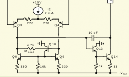
Here are the techniques that I mentioned. In order they are Cordell, Kleinschmiidt, Sansui, and Stochino. The authors may not all be the originators of the ideas but they are the first references that I could find.
Attachments
I see what you mean now.
Turns out I was already experimenting with the 1st option.
So that's what Cordell was proposing to fix that bias issue then.
Adding that resistor increases thd a little, but works.
I don't really understand how those 2nd and 3rd options work, but I really am wary of that 4th, with all those diodes and clamping... I'm thinking that can't be very linear..
I lowered the gain a tiny bit, closer to 6db and this improves noise performance a bit too. The input impedance is a little low, but if we use higher values to increase that, then thd goes up and so does noise.
Difficult compromises...
I also aimed at keeping that class A dissipation down a bit in the outputs, to reduce the need for a heatsink. The vas trannies still would run warm as well.
I'll have to experiment with cascoding instead of the mirrors...
Attachments
Incidentally I was talking utter bo----ks when I said that you needed either a npn/npn or pnp/pnp darlington pair for the Cordell method to work - of course you don't, your configuration is fine. Perils of posting late at night! In fact your npn/pnp darlington configuration has a hidden advantage in that the helper transistor is no longer strictly essential, because you don't need the extra voltage at the mirror collectors to overcome the 2x Vbe at the darlinton input. You just need the resistors R25 and R26 in your simulation. Incidentally you will probably have to reduce them a bit from 100k in real life. You might get away with 10k.
The second of my options works by directly impressing a voltage on the ( high impedance ) mirror collector. I've seen this method used a couple of times in working amplifiers. More parts than Cordell but you don't need the differential load resistor so you get higher open loop gain and lower distortion. So conceptually similar to Cordell with lower distortion but less elegance.
The Sansui method works by cascoding the vas and then making the cascode one leg of a current mirror. The other leg sets the vas current. They took out a patent on this - I can find you a reference if you're interested.
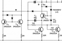
The Stochino method simply makes the vas one leg of a current mirror with the vas current set by the other leg. This is a snip from a working amplifier with 300V/uS slew rate and vanishingly small distortion. The anti-saturation ( Baker clamp ) diodes are everywhere because this is a very fast amplifier and without the diodes clipping would not be very pretty to say the least.
Mid morning so maybe I'm talking less bo----ks now.
The second of my options works by directly impressing a voltage on the ( high impedance ) mirror collector. I've seen this method used a couple of times in working amplifiers. More parts than Cordell but you don't need the differential load resistor so you get higher open loop gain and lower distortion. So conceptually similar to Cordell with lower distortion but less elegance.
The Sansui method works by cascoding the vas and then making the cascode one leg of a current mirror. The other leg sets the vas current. They took out a patent on this - I can find you a reference if you're interested.
The Stochino method simply makes the vas one leg of a current mirror with the vas current set by the other leg. This is a snip from a working amplifier with 300V/uS slew rate and vanishingly small distortion. The anti-saturation ( Baker clamp ) diodes are everywhere because this is a very fast amplifier and without the diodes clipping would not be very pretty to say the least.
Mid morning so maybe I'm talking less bo----ks now.
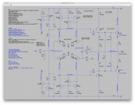
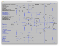
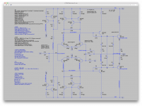
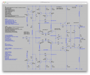
Voltages added to sch (attached).
The resistor values are shown in the variables.
When I may need to change values that affect more than one part at a time, it's easier to put that in a variable, and when that value needs to be stepped, it's unavoidable to do it that way.
I'm about to tweak a version (of the doa) for use on my own cloned 28b, and I will compare using a single tranny+led and the dual tranny ccs.
Using a led may not be quite as good thd wise, but the thermal characteristics might be an advantage... The led and its companion tranny can be thermally bonded for increased thermal stability.
That should be done if possible anyway for the ltp pairs...
Attachments
I'm trying out a few things I saw bryston is supposed to be using now in their "cubed" design, from their patent filed.
I have yet to see any schematics for any of their cubed amps, so I don't know for sure if they actually have used some or all of their patented ideas in the newer models.
But from what I found in their patent, apparently they ditched the concept of "keeping it simple", by no longer using only plain resistor loads in their ltps, switching to mirrors. Plus they add cfp to the ltp, as well as ccs for the ltp tails.
And for the vas, they use a cascoded cfp instead of the plain single.
That does increase the part count significantly and totally departs from their previous approach of "purity" by keeping it spartan.
I will also try out that idea of using the led based ccs instead of the dual tranny, which might perform a bit less well on thd but would likely be more thermally stable.
Yes, that's the patent I was looking into. Trying to figure out exactly what they actually used in their new cubed amps. Since we can't find any schematics for any of those models, we can only speculate what they actually did.
And yes, I think the patent system is broken. They do grant patents to just about anything nowadays and that's been happening for years. Causes too much litigation, over stuff that's public domain really.
And yes, I think the patent system is broken. They do grant patents to just about anything nowadays and that's been happening for years. Causes too much litigation, over stuff that's public domain really.
- Home
- Amplifiers
- Solid State
- Bryston 4B SST clone