Current sources for the ltp tails are an easy mod to the clone pcbs - just use a constant current diode - not the best constant current source but better than a resistor.
I favor the 2 trannies form for current sources. I've done many sims to compare various forms and although it may not be the top performing one and it's a tad more complex than the simple diode based one, it's not really that much higher in part count and those are cheap anyway. We could even cascode that current source, but that might not even be necessary.
One thing that I do with those dual tranny sources is to join their own tails together with a fet based current sources, so the current source's tail itself has a current source as well. Works nicely.
The power supply for those doas should be regulated anyway, so they should always perform at their best.
I'm going to replace the PN100A/PN200A with BC546C/556C, keep the 2N5401/2N5551 in most instances, and replace the MJE172/MJE182 with BD139/BD140 for the output devices of the input opamp.
I prefer using the bc550c/560c, which are lower noise devices.
Using the 5401/5551 is good wherever high voltage can't be avoided.
One thing that could be done with the doas is raise their supply voltages some, which gives even more headroom and reduces distortion a tad more. If the ltps get cascodes, then it's very easy to do it safely, although the bc550c/560c can stand 50V...
I tried using the bd139/140 in the doas in sims, and found they don't perform quite as well as the mje172/182, so I prefer sticking with the mjes there.
I have matched npn/pnp pairs for all of these devices ( hfe only matched so far but I have enough devices to match for Vbe as well ).
That's a must. Has to be done, for best results. Not just for those amps anyway, it should always be done regardless.
Matching both vbe and hfe may be a bit of a burden, but the end result is worth the effort I think.
I'm experimenting with improvements to the DO33 discrete opamp using perfboard and solder and I'll post the results when I have something I'm happy with. I guess we could try opamps with and without the current mirrors so see if there is a noticeable sonic difference. As regards output device matching it would probably be best to buy batches from different suppliers to maximise the chances of getting a match.
The point of the doas is to avoid opamps. But it might be nice to compare...
Should be interesting...
I doubt buying parts from different sources will provide better matches than from the same batches from a unique source.
I would think the chances of better matches would be higher if they're all from the same batches, same date, etc...
To maximize the chances to get better matches, I think there is no better way than getting a larger batch.
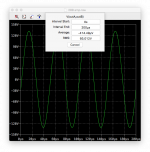
Here an other example of the 28Bsst2 bridge, with a little over 1kW output on 8ohms resistive @20kHz:
Not bad, about 93Vrms on the 8ohms load, more than 1kW, and only about 22ppm thd, and this is at 20kHz. Satisfying. The key is to get a real build to be as close to this as possible. matching parts should go a long way towards that goal..
Making a 28B clone would be aimed at the low end channel, with shitloads of reserve power.
For the highs, we can make a smaller clone, no need for bridging, and using the faster parts (4281/4302).
My speakers for the highs are only 20W capable, but I would make an amp of about 100-150W for that high channel. Transients would almost never get close to clipping. Very comfortable.
It's good to have far more power than needed, it's safer for speakers and can render sharp and fast transients and never get close to clipping.
Attachments
Spookydd why is the thd so high in the sim of post #100? Problem with large batches is that nowadays the processing is so uniform that there is little gain variation within batches. For example, I recently had batches of complementary pairs where hfe for the npns was closely clustered around 200 and all the pnps closely around 300. No possibility of an npn/pnp match. This has been my experience with the majority of cases. Things were better in the old days of 2SA/2SC transistors with their grades of hfe and variations within grades. Sigh.
Has anyone ever tried the version of the complementary differential input stage with current mirror and a darlington vas as described by Douglas Self in his book ( 6th edition pp226-227 )? Basically he puts a current mirror on one set of diff pairs and plain resistors on the other. The resistor side sets the vas current and the other side simply adapts to the set current. Self comments that the circuit is very linear and provides a graph showing very low distortion.
Spookydd why is the thd so high in the sim of post #100?
Have you looked at what level this was taken on?
It's 1.7kW of power output, a little bit before clipping starts really kicking in.
What I posted next was just a tad over 1kW and thd is great. It doesn't rise that much even beyond that, but it's normal when getting close to clipping to see a rise in thd, especially since the protection might also be close to engaging.
That amp isn't supposed to be putting out that much, it's rated for 1kW on 8ohms. They mention onset of clipping at some 1.6kW, so that's a bit lower than my findings because there are more losses in a real amp, with wiring and all that stuff, besides just the rail sagging due to transformer losses and the likes.
Problem with large batches is that nowadays the processing is so uniform that there is little gain variation within batches.
And that's a "problem" because?
Buying from the same batch gives more chances to find the best matches.
For example, I recently had batches of complementary pairs where hfe for the npns was closely clustered around 200 and all the pnps closely around 300. No possibility of an npn/pnp match.
Yeah, that's the bummer part of it. We can fairly easily match same sex, but much more difficult to match between sexes. It takes a bit of luck to find close enough batches for mixed sexes.
Won't stop me from trying to find the best ones though. If a couple of batches don't allow good sets to be found across sexes, then try again later, with an other batch.
This has been my experience with the majority of cases. Things were better in the old days of 2SA/2SC transistors with their grades of hfe and variations within grades. Sigh.
True. I wish they would do more of that, so it would make it easier to get good sets.
One of my projects is a comprehensive full featured and easy to use matching rig, to streamline the matching process, making this as practical as possible, using a computer so the measurements can be put into a database and then use the data to marry sets.
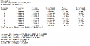
Here's the same 28B bridge on 8ohms @1kHz and a tad above 1kW output:
For this sim, I made it use the PSU sim with the rectifiers and cap banks, plus the regulated parts for the 33V rails feeding the doas. This makes for a very long settling time for the cap banks to charge, and there is a little extra ripple of course, so thd increases a tiny bit, some 1-2ppm thd added. Not much though.
For those 10ms of sine wave that are shown on the plot, 5 times more of that was skipped before that, because the amp isn't functioning quite right with the rising rails.
This is plain vanila 28Bsst2, with the doa68 and how they're basically mated with the power amps as they did with the actual 28b amp.
If we make a few little improvements on the doas, the diff amps stages in the power amps and a few other details, we might be able to improve things a little more. Personally I don't need things like RCA inputs and all those things they add there, especially the gain switching stuff. So I would simplify things quite a bit. I want to remove the electromechanical relays that mute the amps, and replace that by mosfet ssrs on the outputs, on the negative side (no negative side really on a bridge)...
Attachments

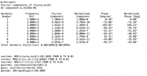
You see, it wasn't a bad thing that thd was rising some at 1.7kW+ output. It doesn't rise until it gets somewhat close to that, right before onset of clipping, quite normal.
Look at ~1.5kW output (same conditions), and we're still not much above 20ppm thd.
It's approaching 160V peak output, and no sign of clipping there.
Look at ~1.5kW output (same conditions), and we're still not much above 20ppm thd.
It's approaching 160V peak output, and no sign of clipping there.
Attachments

Hi..
I adjusted the amp as per debugging 25mv across q19, but have to redo procedure cause its bias first gets rock steady after one hour, idle consumption on wall plug is after one hour 120w.
The measurements I made earlier are not valid, I will increase bias and monitor on spectrum analyser, I'm sure I can reduce it further.
So i build the amp and followed the given schematic and bom list, and don't have the time nor the knowledge to mod it, all i can say is that its playing right now on my huge JBL speakers, and it sounds amazing, clean highs almost 3d on good recordings, so yes specs matters but I trust my ears, my old setup I use as reference was luxman m4000 driving 8 8 inch sealed woofers and tops driven by marantz esotec sm6, tops were jamo concert eight , electronic crosssovers, transsciptor skeleton turntable with creek obh amp, and the clone Bryston matches performance, or better.
But if you guys find any improvements I'm open for modding.
Waiting for outputs for my bryston 28b which also is pr bom and schematic, oh and also nearly finished leach double barrelled amp, always wanted a leach.
Forgot to mention that I'm also working on a different input stage for the 4b, it consists of LME49720NA andLME49600, with adjustable gain, this should be able to drive output stage real nice, but it's not quite finished yet, simulations is a estimate of reality.
Last edited:
I adjusted the amp as per debugging 25mv across q19, but have to redo procedure cause its bias first gets rock steady after one hour, idle consumption on wall plug is after one hour 120w.
When adjusting bias, it has to be done at least twice. First when cold, then wait for a full warm up idle and then tweak some more.
Bit if you have a scope or better to check on things, you can tweak some more when it's at its steady warm temperature and aim for lowest distortion. Make the xover distortion go away.
I prefer making it run warmer, for additional class-A region. It doesn't hurt to raise bias a bit, for more class-A, and make sure xover dist is definitely gone as much as possible. It's not forced ventilated, but with huge sinks, it can run warmer with no problem.
I would always oversize the sinks anyway.
But if you guys find any improvements I'm open for modding.
We can do some, but with an existing pcb, it's hard to do without making a bit of a mess.
Adding current sources on the doas would be an improvement. Plus degen res on the ltps would also be nice, with a tiny bit of tweaking to suit.
Waiting for outputs for my bryston 28b which also is pr bom and schematic, oh and also nearly finished leach double barrelled amp, always wanted a leach.
Sounds interesting, both about the leach and the 28b.
What pcb layout design for that leach?
I assume the 28b is that clone from china on ebay...
It's a beast, with several pcbs, huge psu and toroidal..
Will be designing a 28b module very shortly. With slight adjustments for my taste. 1) I don't need nor want any level adjustments and gain switching, so several parts will be gone between the doas and the amps. 2) no need for other input besides balanced xlr, so simplifying there too. 3) prefer a tad more overall gain, but will also lighten the load on the doas by increasing slightly the amps input impedance. 4) if sims show it's ok, I also would reduce the value of the output coils, maybe 1u or 0.8u instead of the 2u. 5) I might also reduce the value for the 0.3ohms emitter res on the outputs, but that will require adjusting the protections some...
Does anyone fully understand exactly how the protections work, to the point of being able to properly recalculate the point of engagement?
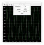
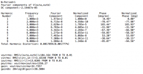
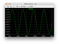
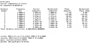
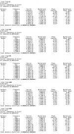
Here's an example of the doa with some slight improvements.
Done @20kHz on 1k5 load.
All trannies are BC550/560 except for the MJE outputs.
Current sources, dual trannies, plus the degen res on the ltp.
With the bias as it is, it has a good class-A region. Most of the time it will work as class-A.
Reflected in the thd figures..
Done @20kHz on 1k5 load.
All trannies are BC550/560 except for the MJE outputs.
Current sources, dual trannies, plus the degen res on the ltp.
With the bias as it is, it has a good class-A region. Most of the time it will work as class-A.
Reflected in the thd figures..
Attachments
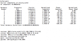
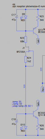
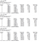
Here's one of the possible improvements for the current sources.
I think I'd favor the dual trannies for the sources instead of diodes or led, but adding a fet between the 2 helps a bit. Better than the plain resistor or grounding each one separately with res..
My plan is to make the doas fully an integral part of the amps, so there will be minimal stuff between the doas and amps. No gain or volume adjustment, and a higher input impedance for the amp to load the doas a bit less, like 1k5 or perhaps 2k, something like that, instead of the 600-700 ohms or so..
Balanced inputs are nice if the signal source is a bit far from the amps or the cabling snakes around many others along the way..
Attachments
Forgot to mention that I'm also working on a different input stage for the 4b, it consists of LME49720NA andLME49600, with adjustable gain, this should be able to drive output stage real nice, but it's not quite finished yet, simulations is a estimate of reality.
Aren't these SMDs?
Is your goal to not use doas?
It's true they do have very low thd. Would be good to know how they compare, with real world listening. (unbiased would be nice)
It's just an experiment, and I'm having trouble driving the amp through sound card, its input impedance is quite low, maybe the mosfet follower (mofo) could help, short reply, got stuff to doAren't these SMDs?
Is your goal to not use doas?
It's true they do have very low thd. Would be good to know how they compare, with real world listening. (unbiased would be nice)

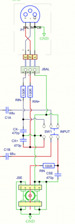
Spookydd I guess JSE means Jack Single Ended, and yes its the symbol for a phono socket. I agree its a weird symbol, maybe all the earths indicate the lugs that are soldered to the pcb for mechanical strength. Didn't read carefully enough before questioning the distortion just before the onset of clipping ( duh! ). Amplitude good to hear about the sound of the Bryston 4Bsst clone. I look forward to your new distortion spectra. No comments on the Self scheme for a single current mirror?
By the way if we do a version of the Bryston front end with current mirrors what do you reckon is the best way to set the vas quiescent current. I have seem various different and tested schemes from Bob Cordell, Glenn Kleinschmidt, Giovanni Stochino, and Sansui ( probably others too ). Any ideas on which is to be preferred?
It's just an experiment, and I'm having trouble driving the amp through sound card, its input impedance is quite low, maybe the mosfet follower (mofo) could help, short reply, got stuff to do
You're trying to drive the 4b clone from a sound card? I assume from a computer..
Your problem is probably mostly more a matter of signal strength, maybe not really the amp's input impedance.
If that clone has the same gain switching and level adjustment as the real thing, there are a few things you could do to tweak this to work better.
I don't think using those opamps will change things much. Unless you're trying to add that in front of the whole thing without bypassing the amp's doa..
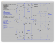
By the way if we do a version of the Bryston front end with current mirrors what do you reckon is the best way to set the vas quiescent current. I have seem various different and tested schemes from Bob Cordell, Glenn Kleinschmidt, Giovanni Stochino, and Sansui ( probably others too ). Any ideas on which is to be preferred?
I did some sims with current mirrors. As I mentioned, they perform exceptionally well. But I was just wondering about the actual sonics, compared to the plain resistive loads on the ltps...
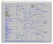
If you wanted to experiment, I have a perfectly working sim that could be put into something to try out. That sim has such low thd, it's almost negligible.
If the real thing could get somewhat close to what the sim shows, it would be outstanding, but remains to be heard what it would sound like. I'm anxious to know..
See attached:
Attachments
- Home
- Amplifiers
- Solid State
- Bryston 4B SST clone