LME49830 Circlotron
Hello,
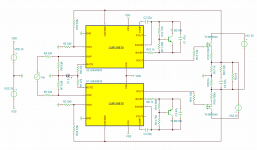
I would like try to sim and amplifier with LME49830 Amplificateur Circlotron Lateral mosFet & LME49830
For the moment I have made a "simple" schematic like the datasheet but there is no quiescent current on MOSFETs
This is the first time I use tina.
Could you check my file?

Thanks
Best regards
Sébastien
Hello,
I would like try to sim and amplifier with LME49830 Amplificateur Circlotron Lateral mosFet & LME49830
For the moment I have made a "simple" schematic like the datasheet but there is no quiescent current on MOSFETs
This is the first time I use tina.
Could you check my file?
Thanks
Best regards
Sébastien
Attachments
Last edited:
no one know tina?
I have play but it is not so nice as LTspice, how to probe things? I can sim and have output but when choose probe there I can see nothing extra when use that probe for voltages.
regards
Do you want the lateral mosfet or the vertical? I have to read paper about the lme what is possible, I did see there also bipolair.
You need to find a lateral model for tina.
In the meamtine I have find out Tina, here I need meters to get the output, but I do no yet now how to probe there, is this only possible with these meters I can add?.
regards
You need to find a lateral model for tina.
In the meamtine I have find out Tina, here I need meters to get the output, but I do no yet now how to probe there, is this only possible with these meters I can add?.
regards
I do not know Tina at all, so I do not know how to do an analysis
for the moment lateral or vertical does not matter, the LME is made for both MOSFET
AN-1850.pdf :
https://archive.eetasia.com/www.eet..._2008OCT30_POW_ACC_AN_01.pdf?SOURCES=DOWNLOAD
for the moment lateral or vertical does not matter, the LME is made for both MOSFET
AN-1850.pdf :
https://archive.eetasia.com/www.eet..._2008OCT30_POW_ACC_AN_01.pdf?SOURCES=DOWNLOAD
Attachments
Later today you get anwser, I see you have differnetial supply for the chip, and floating supplys on output because of circlotron the ground reference resistors are quite high, need to drive the gates properly can be issue also normally you have two halves also the chip, how to do that properly as the chip is not made for circlotrons. I am a litte curieus now maybe because you use just the single output, and does this not danger the chip.
I get the hang for Tina already, just play with as it is your woman.
regards
I get the hang for Tina already, just play with as it is your woman.
regards
Last edited:
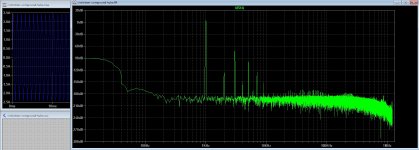
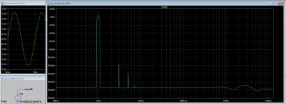
I have doen the sim.
It does work so at hand, but I doe not now why there is no voltage over the Vbe multiplier, maybe beause of model or the open P output.
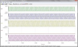
it does with 1 volts in give 30 volts out, try in multisim.
VM3 is the meter over the vbe transistor, as you see no voltage and you see the crossover clearly om VM1 wich voltage is symmetric from zero volts.
regards
It does work so at hand, but I doe not now why there is no voltage over the Vbe multiplier, maybe beause of model or the open P output.
it does with 1 volts in give 30 volts out, try in multisim.
VM3 is the meter over the vbe transistor, as you see no voltage and you see the crossover clearly om VM1 wich voltage is symmetric from zero volts.
regards
Attachments
It looks like Vbe fuction is not in model, it does nothing also with the schematic in examples.
But it does work, I think just build one channel and see.
What concern Tina. the wireing and placing components is not mine favorite, program is difficult and LTspïce is a lot better with probing and so.
regards
But it does work, I think just build one channel and see.
What concern Tina. the wireing and placing components is not mine favorite, program is difficult and LTspïce is a lot better with probing and so.
regards
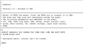
texas did not give anything else 
LME49830 | Mid/High-Power Class D Amplifiers | Audio | Tools & software
LME49830 | Mid/High-Power Class D Amplifiers | Audio | Tools & software
Attachments
apart from the circlotron scheme, I've never seen that LM with lateral fet use vbe multiplier
The_Wire_LME_Lateral_FET_Amp Wiki
The_Wire_LME_Lateral_FET_Amp Wiki
There is no thermal bias compensation required, and no emitter resistors needed thanks to the lateral mosfets.
For lateral fet you need none, for irfp240 you need one, that is why we did try vertcals. But for these fets, do check if these has gate protection diodes otherwise put on yourselfs.
I have looked on the lme chip itselfs, the outputs are currend source loaded where the bias resides, in circlotron we use just one side, x 2 for the other one, if the idle voltage do not cancel out, we can set bias idle.
Laterals sound much better in mine eyes, I have try this some time ago.
regards
Attachments
Last edited:
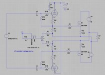
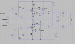
And with post 16 driver you can nicely steer this compound output circlotron.
it as 2 x amplification factor, with local feedback you can make some nice stuff.
output pic is 1 x version, feedback resistors can be adjusted, you need 2 watt resistors here, or even more.
it as 2 x amplification factor, with local feedback you can make some nice stuff.
output pic is 1 x version, feedback resistors can be adjusted, you need 2 watt resistors here, or even more.
Attachments
Last edited:
Nice output stage, i already try to simulate a compound in this schematic, but no result :
http://circlotron.audio/data/simulation/asc/bjt_circlotron_1.1A.asc
http://circlotron.audio/data/simulation/img/bjt_circlotron_1.1A.png
moreover I still have not succeeded in replacing RB by a bias system
: http://circlotron.audio/data/simulation/asc/bjt_circlotron_1.1A.asc
http://circlotron.audio/data/simulation/img/bjt_circlotron_1.1A.png
moreover I still have not succeeded in replacing RB by a bias system

Nice output stage, i already try to simulate a compound in this schematic, but no result
http://circlotron.audio/data/simulation/asc/bjt_circlotron_1.1A.asc
http://circlotron.audio/data/simulation/img/bjt_circlotron_1.1A.png
moreover I still have not succeeded in replacing RB by a bias system
Do work in it.
the bias can be done with a current source ? for output I have put them in, see .asc voltage will be swapped on N or a P mosfet, bias is then close to two, otherwise it has to be negative or positive, can be done with current source who is temp sensor also>?.
Have no other work, maybe look at it later.
regards
Attachments
- Status
- This old topic is closed. If you want to reopen this topic, contact a moderator using the "Report Post" button.
- Home
- Amplifiers
- Solid State
- LME49830 in TINA