Through Q1 and Q2 goes the same current of 2 mA each.
If that would be true, Q3 would be completely saturated and useless.
Jan
Where is your circuit diagram coming from?
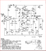
This is the input section of the amps from a Heathkit AR-1500A that I built in 1971 and cleaned up recently.
On the LTSpice attached, the transistor types are as close as I could come to the original Heathkit types.
Attachments
Last edited:
dc offset
You have the actual hardware available - this will give a more credible result than a simulation - what are the dc levels on the output terminals and is the value of R13 10k in this.
Taking a few voltage measurements to show drops across components and applying Ohms law is a lot easier than going to the trouble of drawing up simulation.
The simulation looks like an RCA application and I have attached a copy to allow comparisons between the two. One notable difference in the application is the value for R13 of 12k rather than 10k in the simulation.
Looking at the simulation as an exercise in theory, the level of dc at the output is too high. I think this is out of line because of the choice of .models and that you will need to find more accurate ones.
Anyway working with your simulation within the limits of its accuracy, increasing R13 to 12k reduces that a bit and 18k will get the current levels in Q701 and Q702 close to equality.
In the present setting is the consequent reduction of the LTP tail current will erode the slew rate - you can cross the 18k change out.
You can measure voltages at points to work out currents passing through resistors using Ohms law and compare the results with your simulation to see where the differences lie.
This is the input section of the amps from a Heathkit AR-1500A that I built in 1971 and cleaned up recently.
On the LTSpice attached, the transistor types are as close as I could come to the original Heathkit types.
You have the actual hardware available - this will give a more credible result than a simulation - what are the dc levels on the output terminals and is the value of R13 10k in this.
Taking a few voltage measurements to show drops across components and applying Ohms law is a lot easier than going to the trouble of drawing up simulation.
The simulation looks like an RCA application and I have attached a copy to allow comparisons between the two. One notable difference in the application is the value for R13 of 12k rather than 10k in the simulation.
Looking at the simulation as an exercise in theory, the level of dc at the output is too high. I think this is out of line because of the choice of .models and that you will need to find more accurate ones.
Anyway working with your simulation within the limits of its accuracy, increasing R13 to 12k reduces that a bit and 18k will get the current levels in Q701 and Q702 close to equality.
In the present setting is the consequent reduction of the LTP tail current will erode the slew rate - you can cross the 18k change out.
You can measure voltages at points to work out currents passing through resistors using Ohms law and compare the results with your simulation to see where the differences lie.
Attachments
Last edited:
Thanks for the reply. Yes, it sure does look like the RCA app. For the sim, I was not able to find models for all Heathkit transistors, so the ones in the sim are not the same as in the real hardware. In addition, the input pair in the sim would be 'matched', while in the real hardware they are not. Despite that, the voltage/current readings on the real hardware are close to the values on the sim. The sim shows an output offset of -222 mV, the real unit had one channel at -130 mV, the other at -90 mV if I remember correctly.
And yes, increasing the 10K to 15K improved the offset, as did changing the 680 to a 470. But I do not have the theory or the test equipment to determine what effect those changes would have on stability, so I left the factory values. Did end up injecting a bit of current into the FB input to reduce the offsets.
And yes, increasing the 10K to 15K improved the offset, as did changing the 680 to a 470. But I do not have the theory or the test equipment to determine what effect those changes would have on stability, so I left the factory values. Did end up injecting a bit of current into the FB input to reduce the offsets.
I substituted some .models from Bob Cordell's website and the dc offset with R13=10k then=12k the simulation results were -150 m.V. and -97 m.V. There are a couple of departures from the RCA stability set up in the Heathkit amplifier. The impacts of Miller capacitance of C4 etc need considering.
Apart from the usual negative feedback connection to the output there are two other paths linked to the collector of Q703 and the other connected to the emitter.
The feedback from the output is in opposite phase to the signal generated at Q703 collector increasing the load impedance at that point - referred to as a bootstrap arrangement.
The other connects to Q703 emitter where the output signal is opposite in phase to that at the collector.
If you look at the component in the connecting paths using the pick the visible traces in the toolbar you can see effects that are not apparent if you use the cursor to hover over components.
In the image attached I(R8) overlays I(C2) showing a variation on 1kHz sine with 1V input of peak to peak current swings of 100 m.A.
This design may be interesting - Nelson Pass first Class A amplifier which dates from 1977? includes some of the features used here - you can look this up on his website.
I had a friend who built one over 40 years ago - he knew nothing about how that worked but he had the faith to build this and it did.
I don't have Self's books but have read some of his writings and find his style quite straight forward. His designs also look that way - how to apply the learning from a Self design to a subject like the Heathkit circuit may not be so easy.
Interesting that C2/R8 forms a positive FB path. I understood the bootstrap function of C1, but never did understand why C2/R8 were there. Didn't recognize it as a FB path until you mentioned it.
Thinking about it last night...
C2/R8 is not a true feedback path. Similar to the way in which C1 acts as a bootstrap for positive excursions of the output, C2/R8 working against R21 act as a bootstrap for the negative excursions.
While the voltage at the emitter of Q703 is modulated by the output signal, the same change is appearing at both ends of R15. Since the collector of Q1 is a current source, and the output of the Q703 is also a current, changes in the emitter voltage of the VAS have no effect on the output of the VAS.
Oh, and the miller cap (Cdom) in the RCA circuit is the 39 pF C3. Equivalent to C4 in the Heathkit.
But none of that explains why the static operating point of the input LTP is so extremely unbalance by design.
How does the oscilloscope measure SR, is there a specific introduction?
The circuit I made has an ultra high frequency signal. I connected the 470P capacitor to the CE terminal of the TR4, and the signal disappeared. Is this OK?
Why R 16 and R17 are very hot, 1.5A current calculation power is only 0.225W, but I use 5W resistor is very hot. I used a 20M oscilloscope and didn't see the oscillation. Why is this happening?
Attachments
- Status
- This old topic is closed. If you want to reopen this topic, contact a moderator using the "Report Post" button.
- Home
- Amplifiers
- Solid State
- Douglas Self Sixth Edition