This is exactly what I've been looking for! my question about the vbe multiplier is should the transistor be mounted on the same heatsink as the power transistors? or do you just mean keeping it cool will keep it stable. While i'm at it, can I just attach all power transistors to one beefy heatsink? I know the back of components are sometimes attached to one of the pins for some reason.
Also how would I go about choosing "perfect" transistors for this amplifier? I will be building one with all 3904s/3906s/3055s because thats what my school has in stock, but I want to replace the 3904s and 3906s with something more "rugged".
Also how would I go about choosing "perfect" transistors for this amplifier? I will be building one with all 3904s/3906s/3055s because thats what my school has in stock, but I want to replace the 3904s and 3906s with something more "rugged".
All those devices you mention are rugged enough for a simple amplifier like this running on low voltage supplies. In fact they are ideal for this project. If you moved to higher voltage supplies then the drivers could be substituted for something like BD131 and BD132
Yes, the output transistors can be on one heatsink but remember they all need insulating kits to isolate them electrically. The collector of each is connected to the metal case.
You might find the flatpack type devices easier to use (TIP41 etc) rather than the 2N3055 style. Just one hole to drill for each rather than four.
The vbe multiplier can also be a small power transistor (for easy mounting) and ideally should be mounted between the two output transistors on the same heatsink. The drivers don't need additional cooling for the amplifier as it stands and running on 12 volts.
so I built this full circuit, using 3904s and 3906s with TIP31s for the two output transistors, that Mooly posted with the VBE multiplier, and I changed the 1K collector resistor to (2) 560Rs and a 100uF cap going to the output cap (not speaker side), here are my findings:
no changing of the preset resistor affected amplifier, when I disconnected on of the pins and nothing changed I realized the amp was just using it as a single diode bias, so I omitted it and tried diodes, as expected this just created what i'm assuming is crossover distortion so complete removal of the bias circuit was opted for.
Complete removal of the TIP31 with the 1 ohm emitter resistor going to ground does not affect performance at all.
the 10K feedback resistor going to the input transistor was changed to a potentiometer, I found anything over 220 Ohms increased power output greatly but also increased distortion greatly.
EDIT: I should note that the distortions I am talking about I ruled out overdrive.
Max undistorted output is 6v p2p.
this circuit has a max undistorted input level of 3 volts, for the applications I plan on using this circuit for this is desired.
Should I have heard a difference when the preset resistor of the VBE multiplier was changed? My meter has a blown fuse at the moment so I cannot measure the 20mA on the emitter resistors, I just figured I could dial it in by ear/with the scope. The circuit generates almost no heat (my shop is rather cold but I don't feel any heat to the touch) but i'm aware if I start increasing the power output somehow I will probably need the VBE multiplier for thermal runaway protection, so how can I get this working?
How can I increase the 6v output to closer to 10v or increase power output?
alternatively, it seems if I could remove the distortion from having a high feeback resistor value I would have the output power that I want (there is a significant volume drop with all distortion removed).
I do appreciate all this help.
Attachments
Last edited:
Congratulations on a successful bare bones build.so I built this full circuit, using 3904s and 3906s with TIP31s for the two output transistors, that Mooly posted with the VBE multiplier,
How can I increase the 6v output to closer to 10v or increase power output?
.
You could get more power by changing drivers from 2n3904/06 to a heat sinked transistor like TIP31, and cutting the emitter resistors on the drivers from 470 to 220 ohms. Usually having the drivers on a separate heat sink from the output transistors provides reliability advantages. Keeps thermal runaway from being quite so prevalent. I make heatsinks for drivers by cutting up scrap aluminum from window frames etc, then drilling holes in them. But you do need heatsink compound. Warning, heatsink compound is poisonous, don't touch mouth nose or eyes before washing hands. For heatsinks out in the open air you don't need insulators.
Usually in class AB, you can only get about 1/2 the power supply (rail voltage) voltage out. At 6 v peak to peak, you are below that, since that is 4.2 average voltage.
I'm using tip41c/42c for drivers on an AX6, driving TO3 MJ802 equivalent output transistors. But the heatsink for that was pre-drilled, a burnt up semiconductors dynaco ST-120. AX6 has same number of transistors per channel than your design. Very similar. I'm getting 70 W for a second at a time out of my AX6 on 8 ohm load with 70 v rail. For that I used heat sink on the VAS, too. A D44-R2. Retro Amp 50W Single Supply My AX6 card is post 212. Schematic is page 1. It has a few more resistors and caps than your design. I'm listening to the AX6 tonight, Little Steven's Underground Garage show just went off. Very pleasant sound.
For higher rail voltages than 12 you'll want to move to higher power output transistors. Biggest bargain in the US on single hole TO264 cases are MJL4281 npn MJL4302 pnp, or in TO3P cases MJL21194 npn MJL21193 pnp. You'll need to3-p heatsink pads for those.
I found some oddball 44 V CT transformers on e-bay for $10 that would give you about 62 v peak. Or you can buy what transformer you want from antekinc.com
Last edited:
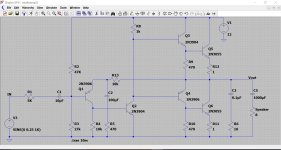
so I built this full circuit, using 3904s and 3906s with TIP31s for the two output transistors, that Mooly posted with the VBE multiplier, and I changed the 1K collector resistor to (2) 560Rs and a 100uF cap going to the output cap (not speaker side), here are my findings
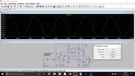
We can add what you did to the simulation. Notice the Vin and Vout nodes. The Vin node is the true input point of the amplifier.
For the purposes of the simulation I've also increased the value of a couple of caps (don't do this in the real amp) and also increased the load to 100 ohms.
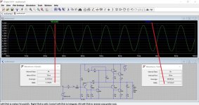
The input voltage is 147.53mv rms and the output is 3.193 volts rms. If we divide them we get the voltage gain of 21.7
Now look at the feedback resistor R13 and the feedback return R5.
The gain of the amplifier should equal 1+(R13/R5). If you work it out you will see its pretty close
")
no changing of the preset resistor affected amplifier, when I disconnected on of the pins and nothing changed I realized the amp was just using it as a single diode bias, so I omitted it and tried diodes, as expected this just created what I'm assuming is crossover distortion so complete removal of the bias circuit was opted for.
Complete removal of the TIP31 with the 1 ohm emitter resistor going to ground does not affect performance at all.
If you mean that removing Q6 in my diagram did not change things then that points to a construction error somewhere.
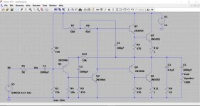
The Vbe multipler should allow significant current to be able to flow in the output stage.
You can derive the current in the 1 ohm by measuring the voltage across it and using ohms law. 20 milliamps would be 20 millivolts (V=I*R).
You should be able to measure and see change the voltage across the vbe multiplier as you turn the preset and for this type of amplifier you need to be getting around .
If you want to alter the gain then altering the 470 ohm is the way to do it... but be careful as to little gain can cause stability problems.
Last picture shows the typical DC voltages present.
Attachments
Sorryto bring up kind of a dead thread. But I soldered up a prototype of the circuit using 3904s, 3906s, and BD139s for the output devices and vbe multiplier mounted between them. I have R5 changed to a 220ohm fixed + 500ohm trimpot for variable gain as well as what I believe is R6 changed to a 10K trim for bias.
When testing both by myself and with my teacher the following measurements are made:
1vac in 500hz (this is the max undistorted input with circuit built correctly)
~3.6vac out
~260mA out
8 ohm load
Measured with multimeter
So about .9 watts this amplifier outputs right? I would believe it but at 9v (not that stable at 12v I found) this amplifier is way louder than any LM384 5 watt amplifier myself and my teacher are used to (trying to get more audio projects in the program than 386 and 384 circuits). It also generates way more heat.
Are we measuring the output power wrong? I also tried it with a 60Hz input but I got similar results.
Glad to hear a student making progress!
(V^2)/R gets 1.6 W. (I^2)*R gets .54 W. Your 8 ohm speaker is not a pure resistor, so somewhere between the two is the actual watts.
If you're using a 12 v supply, you could theorectically get more like 6 vac out or 4.5 W perhaps. Follow Mooly's suggestion about increasing gain of VAS and mine about the drivers, and try for a bit more.
Or convert to an AX6 with about 6 more parts and TIP31C/32C as drivers, 2n3055 as outputs (or MJL4281 more practically, one hole mount) , and go for 70 W off a 70 v rail. (which is what I am getting). At the end of the thread linked to in post 24, Apex posted a 25 W amp using lower rail voltage which maybe you could get off a heating/cooling 24 vac transformer from the home store. Your critical part for more power might be a 120 vac (240 vac in eastern hemisphere) fan. Or 12 vdc if there is a junkyard with fans for cooling car drivers.
What continent are you on? In Eurasia 2SC5200 are cheaper than MJL4281, here they are the same price and MJL4281 has more power capability so I don't buy 2sc5200.
Last edited:
Sounds like you are having fun with the amp
Running on 9 volts gives an absolute limit (theoretical) of 4.5 volts peak amplitude. Divide that by root 2 and we get the maximum RMS voltage available (your DVM will display sinusoidal waveforms as RMS values). So 3.18 volts RMS is the theoretical maximum available.
In practice there are losses such as transistor saturation and resistive loses in the emitter resistors. So your measured 3.6 volts sounds a bit high for a 9 volt rail.
You mention it wasn't stable at 12 volts. What was it doing?
Any instability or oscillation could give misleading results on a meter,
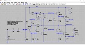
It might worth adding a 'Zobel Network' to the output as shown here. This shows the Zobel and the maximum undistorted output when running on 9 volts. The Zobel is a 0.1uF and 10 ohm (not very critical, 4.7 to 10 ohms is fine). Also be sure to trim R3 to get the maximum undistorted swing in each direction. This occurs when the midpoint voltage (the output of the amp before the speaker coupling cap) is approximately half the supply voltage.
If you have the bias current set correctly then the amp should run very cool at idle and only get warm when delivering current to the load.
Load current in this example was 288ma RMS. Note that many budget DVM's can be inaccurate on low AC voltages.
Running on 9 volts gives an absolute limit (theoretical) of 4.5 volts peak amplitude. Divide that by root 2 and we get the maximum RMS voltage available (your DVM will display sinusoidal waveforms as RMS values). So 3.18 volts RMS is the theoretical maximum available.
In practice there are losses such as transistor saturation and resistive loses in the emitter resistors. So your measured 3.6 volts sounds a bit high for a 9 volt rail.
You mention it wasn't stable at 12 volts. What was it doing?
Any instability or oscillation could give misleading results on a meter,
It might worth adding a 'Zobel Network' to the output as shown here. This shows the Zobel and the maximum undistorted output when running on 9 volts. The Zobel is a 0.1uF and 10 ohm (not very critical, 4.7 to 10 ohms is fine). Also be sure to trim R3 to get the maximum undistorted swing in each direction. This occurs when the midpoint voltage (the output of the amp before the speaker coupling cap) is approximately half the supply voltage.
If you have the bias current set correctly then the amp should run very cool at idle and only get warm when delivering current to the load.
Load current in this example was 288ma RMS. Note that many budget DVM's can be inaccurate on low AC voltages.
Attachments
- Status
- This old topic is closed. If you want to reopen this topic, contact a moderator using the "Report Post" button.
- Home
- Amplifiers
- Solid State
- Transistor amplifier design