Hello.
I haven't been able to find any threads, regarding my question about my first A/B design.
It's very simple, and only early state - it is my basic design to try things out, see what i like, what i don't like so i can get some experience my self. That's the reason there is no outputfilter, DC prot. oversurge, ETC..
But, when i simulate it i have a very high current draw in idle, why i haven't build it yet.. Can any one see any reason for this?
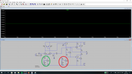
I have attached a schematic , where:
The red current source is design for 10mA
The green current source is design for 2mA
If i disable either, then my current draw is right.
Any suggestion will be appreciated!
Best regards
Whazz
I haven't been able to find any threads, regarding my question about my first A/B design.
It's very simple, and only early state - it is my basic design to try things out, see what i like, what i don't like so i can get some experience my self. That's the reason there is no outputfilter, DC prot. oversurge, ETC..
But, when i simulate it i have a very high current draw in idle, why i haven't build it yet.. Can any one see any reason for this?
I have attached a schematic , where:
The red current source is design for 10mA
The green current source is design for 2mA
If i disable either, then my current draw is right.
Any suggestion will be appreciated!
Best regards
Whazz
Attachments
Hello.
I haven't been able to find any threads, regarding my question about my first A/B design.
It's very simple, and only early state - it is my basic design to try things out, see what i like, what i don't like so i can get some experience my self. That's the reason there is no outputfilter, DC prot. oversurge, ETC..
But, when i simulate it i have a very high current draw in idle, why i haven't build it yet.. Can any one see any reason for this?
I have attached a schematic , where:
The red current source is design for 10mA
The green current source is design for 2mA
If i disable either, then my current draw is right.
Any suggestion will be appreciated!
Best regards
Whazz
There is just a little bit more than what your simulation shows.
Just too many things are missed or mis (placed). The CFP output is an
oscillator if not just right.
(It might not work - as an amp , that is).
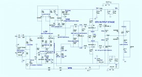
(below) is the simplest of the simple. Very few components are there
for "show". Omit some , bad performance ..... others - much smoke !!
The .ASC and the models text are also below , run them together on your desktop. Just click and run. Set at 1Khz , very low THD.
Reverse engineer this basic example into (anything - 6 amps at ,least).
Any questions , just ask.
PS - you have no emitter degeneration on any devices , it really could not work.
You need lots of resistors !!
OS
Attachments
Last edited:
...very high current draw in idle, ...The red current source is design for 10mA....
Then Q5 must be passing 10mA. Assume hFE of Q5 is 100. The base sucks 0.1mA. Through a 7.5k resistor. This alone is 0.75V.
The real goal is 2*Vbe across Q5. Two *small* equal-value resistors would do this. But high-value resistors give added voltage, the extra 0.75V. Across 0.44 Ohm emitter resistors, this is 1.7 Amps. (What does your sim say?)
Study known-good plans and adopt similar values until you understand "why?" thos values were picked. R6 R5 probably ought to be 1k or less (but not as low as 100r).
- Status
- This old topic is closed. If you want to reopen this topic, contact a moderator using the "Report Post" button.