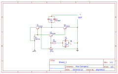
Hi I'm new on this forum, I'm not very experienced. I found this simple online scheme and I made it with recovery components. The sound is very good, does anyone have suggestions or improvements? The original components are referred to as 2sc5200 for power and 2sc4883 for the pilot.
Thank you
Thank you
Attachments
")
Can anyone do a simulation? I have no tools to do it
Installing and using LTspice IV (now including LTXVII). From beginner to advanced.
There's an excellent guide how to set up and use free simulation software, LTSpice. It has been really useful for me and lots of fun also.
https://sound-au.com/tcaas/jlh1969.pdf
This is where your circuit comes from. You can probably use the same transistors with the addition of BC560 for TR4.
Use BIG heatsinks and watch your standing current.
This is where your circuit comes from. You can probably use the same transistors with the addition of BC560 for TR4.
Use BIG heatsinks and watch your standing current.
I don't know about real A...My Pyle rack is A/B...one of those pretty Bubbly sounding ones too with dirt..that input is rocking a tlo84 that contributing...I'm gonna try to overfilter it....
And I don't know totally unmarked IC's and no schematic...
Home stereo like with just two 6800uf....that's still kinda LIGHT...we can go up to 10,000uf easy.
And I don't know totally unmarked IC's and no schematic...
Home stereo like with just two 6800uf....that's still kinda LIGHT...we can go up to 10,000uf easy.
Regulated Power Supplies make a huge audible difference to small Class A amps.
You might like to use 2 off
100V-240V AC to DC 14V 4A Power Supply Adapter Converter 5.5*2.5-2.1mm US EU | eBay
or if you are feeling brave
60W AC to DC 15V 4A Power Supply Adapter Charger Converter Cord for LCD TV GPS | eBay
as your power supply
You might like to use 2 off
100V-240V AC to DC 14V 4A Power Supply Adapter Converter 5.5*2.5-2.1mm US EU | eBay
or if you are feeling brave
60W AC to DC 15V 4A Power Supply Adapter Charger Converter Cord for LCD TV GPS | eBay
as your power supply
> do a simulation?
EasyEDA is supposed to have a simulator in it?
I have no doubt it works. The bias current is easily figured: voltage on 680r resistor, half, times hFE of the output devices. The center-point voltage looks very unstable: the input to the 'pilot' is about 400 Ohms, so a pot 100X bigger will be hypersensitive.
All the performance equations involve hFE. Current gain is hFE1*hFE2. hFE of parts with the *same* number on them may vary 3:1. So it will be hard to make two amplifiers come out the same.
It is reminiscent of the JLH, but without the input stage, so center-point bias and voltage gain are not as well controlled.
Sure looks like fun!
Attachments
Compensate it and use an inductor to isolate the output load.
Try lowering the bias pot by 10x (input impedance down to 2k can easily be driven by most sources nowadays.
I agree with the earlier comments: this will not be very DC stable. You could derive the bias of the input transistor from a forward biased diode to provide 1st order compensation but that will require more components and or split rails.
Have you looked at the PSRR?
Anyway, good learning exercise - good luck!
Last edited:
The Df makes it unusable with most speakers.
The fact that electrical measurements speak negatively, does not mean that it is unusable. I invite you to take similar transistors and try, you could be happy with the result.
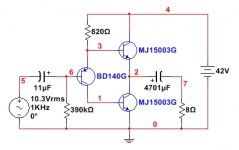
This is a very crude amp and the "standing" current in Q1 and Q2 will be huge and unpredictable. Adding resistors to the base and emitter of Q2 will help but the circuit will still behave strangely if the load isn't exactly what you planned. Assuming you use an 8 Ohm load, the ideal standing current should be about 42/2/8/2= ~1.3 Amps for a class A amp. More is just heating your living room. So if you use a 1 Ohms emitter resistor, the base resistor should be ((1.3*1)+0.65)/(21/680) = ~63 Ohm. Refine this estimate in simulation.
I suspect that this scheme, apart from being very unstable in DC, must achieve very little output power before the distortions become noticeable (in the best case, it must reach 1/4 W over 8 ohms with THD less than 1%).
It is too much dissipation for so little purpose.
Although not yet being totally to my liking, I would change that amplifier to a buffer, replacing the NPN input transistor with a PNP (inverted, of course). Thus, although it remains unstable in DC, it would reach up to 13.26 W RMS on the same load and with similar distortion. The requirement, now, would be to have a previous stage with voltage gain.
Play with the final value of the 390K resistor, since its value depends on the parameters of the associated transistor. The same with the 820 ohm resistor.
Attachments
Last edited:
- Status
- This old topic is closed. If you want to reopen this topic, contact a moderator using the "Report Post" button.
- Home
- Amplifiers
- Solid State
- minimal class a amp