You're measuring in the correct place 
We need to nail this one...
If you can achieve 4.756 volts across C752 then things should be happening. Remember that is the voltage across the cap as measured with a meter lead on each end.
Here is what we do. This should show us why the output transistors are still not conducting.
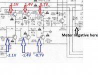
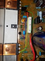
1/ Connect your meter negative lead to the middle pin of the resistor network which is the main amplifier output and leave it there.
2/ We now measure and record the voltage on each transistor base as shown. Each time we move back toward C752 we should see another (approximate) 700mv added to the total.
Measure initially where it is easiest to get at, for example on the resistors that connect to the base's.
So six readings in all. Your measured 4.756V should allow an average of almost 0.8 volts per transistor which should be enough for it to bias correctly. So lets see where it falls down.
The voltages on the upper three transistors will be positive in value, those on the lower negative.
We need to nail this one...
If you can achieve 4.756 volts across C752 then things should be happening. Remember that is the voltage across the cap as measured with a meter lead on each end.
Here is what we do. This should show us why the output transistors are still not conducting.
1/ Connect your meter negative lead to the middle pin of the resistor network which is the main amplifier output and leave it there.
2/ We now measure and record the voltage on each transistor base as shown. Each time we move back toward C752 we should see another (approximate) 700mv added to the total.
Measure initially where it is easiest to get at, for example on the resistors that connect to the base's.
So six readings in all. Your measured 4.756V should allow an average of almost 0.8 volts per transistor which should be enough for it to bias correctly. So lets see where it falls down.
The voltages on the upper three transistors will be positive in value, those on the lower negative.
Attachments
You're measuring in the correct place
We need to nail this one...
If you can achieve 4.756 volts across C752 then things should be happening. Remember that is the voltage across the cap as measured with a meter lead on each end.
Here is what we do. This should show us why the output transistors are still not conducting.
1/ Connect your meter negative lead to the middle pin of the resistor network which is the main amplifier output and leave it there.
2/ We now measure and record the voltage on each transistor base as shown. Each time we move back toward C752 we should see another (approximate) 700mv added to the total.
Measure initially where it is easiest to get at, for example on the resistors that connect to the base's.
So six readings in all. Your measured 4.756V should allow an average of almost 0.8 volts per transistor which should be enough for it to bias correctly. So lets see where it falls down.
The voltages on the upper three transistors will be positive in value, those on the lower negative.
Upper transistors:
Q762 = 333mV
Q758 = 333mV
Q754 = 8.33V
Lower transistors:
Q764 = 334mV
Q760 = 334mV
Q756 = 3.76V
Additional info:
key for below: ref, part number, transistor type, left to right pin numbering and configuration.
Q758 = BD139 - PNP (123,BCE)
Q760 = BD140 - NPN (123,BCE)
Q762 = MJL21194 - NPN (321, ECB)
Q764 = MJL21193 - PNP (321, ECB)
Q754 = 2SC2240 (from QN01) - NPN (123, ECB)
Q756 = 2SA970 (from QN03) - PNP (123, ECB)
Last edited:
IGNORE THIS POST AS RESULTS ARE INCORRECT AND I AM UNABLE EDIT THE POST ANYMORE.Upper transistors:
Q762 = 333mV
Q758 = 333mV
Q754 = 8.33V
Lower transistors:
Q764 = 334mV
Q760 = 334mV
Q756 = 3.76V
Additional info:
key for below: ref, part number, transistor type, left to right pin numbering and configuration.
Q758 = BD139 - PNP (123,BCE)
Q760 = BD140 - NPN (123,BCE)
Q762 = MJL21194 - NPN (321, ECB)
Q764 = MJL21193 - PNP (321, ECB)
Q754 = 2SC2240 (from QN01) - NPN (123, ECB)
Q756 = 2SA970 (from QN03) - PNP (123, ECB)
Hmmm... we have multiple problems here. So one step at a time.
Q754 is the one to work with at this stage. Your reading shows the base is almost 8 volts higher than the emitter.
Can you do a double check and measure the voltage between base and emitter of that device. That's reading between the two top left arrows in the above diagram.
Your readings above suggest there is around 8 volts present across the junction. That's very odd, it should limit at under a volt by the diode action of the junction.
(Be sure all the semiconductors really are correctly placed. The BD139 is an NPN type, the BD140 is the PNP)
(Be sure all the semiconductors really are correctly placed. The BD139 is an NPN type, the BD140 is the PNP)
I bought in an amp that wasn't working and had a similar problem with BE voltages. Turned out someone had previously tried to repair it and put in a pnp instead of an npn transistor. To help the number had rubbed off the transistor. It "diode" checked ok but when I looked into it further the diodes were backwards on the check.
Upper transistors:
Q762 = 333mV
Q758 = 333mV
Q754 = 8.33V
Lower transistors:
Q764 = 334mV
Q760 = 334mV
Q756 = 3.76V
Additional info:
key for below: ref, part number, transistor type, left to right pin numbering and configuration.
Q758 = BD139 - PNP (123,BCE)
Q760 = BD140 - NPN (123,BCE)
Q762 = MJL21194 - NPN (321, ECB)
Q764 = MJL21193 - PNP (321, ECB)
Q754 = 2SC2240 (from QN01) - NPN (123, ECB)
Q756 = 2SA970 (from QN03) - PNP (123, ECB)
Hmmm... we have multiple problems here. So one step at a time.
Q754 is the one to work with at this stage. Your reading shows the base is almost 8 volts higher than the emitter.
Can you do a double check and measure the voltage between base and emitter of that device. That's reading between the two top left arrows in the above diagram.
Your readings above suggest there is around 8 volts present across the junction. That's very odd, it should limit at under a volt by the diode action of the junction.
(Be sure all the semiconductors really are correctly placed. The BD139 is an NPN type, the BD140 is the PNP)
Q754 B-E voltage = 371mV
Redo of voltage test of centre pin of R766 resistor network to base of 3 pairs of transistors:
Upper transistors:
Q762 = 334mV Tested from: R766
Q758 = 8.0V Tested from: Q754 emitter
Q754 = 8.33V Tested from: R758
Lower transistors:
Q764 = 336mV Tested from: R774
Q760 = 400mV Tested from: R762
Q756 = 3.753V Tested from: R760
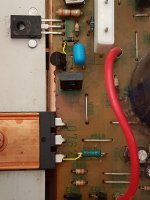
I have attached photos of testing points.
Attachments
Last edited:
OK ")
Try and stay with me here...
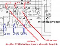
So when you measure back from R768 (the resistor network) we see a massive jump to 8 volts when we get to Q754. Lets stay with that result.
You then measure the B-E voltage on Q754 directly and get around 300mv.
So something is amiss here. Look at my diagram with the arrows. R758 should connect to the base of Q754. Now look where the emitter goes. The emitter of Q754 goes to the base of Q758 and that has been measured at just 8mv.
So the results aren't agreeing... and that could be good because maybe there is a break in the print around there.
You need to very carefully measure and see if there really is a break. You can do this two ways and it might be good to actually do this. One way is by simply measuring resistance from point to point and the other is looking for big volt drops between the same points.
For example you should have continuity from the leg of R758 (100 ohm) to the base leg of Q754. There should also be zero volts between those points.
Now do the same between the emitter leg of Q754 and the base leg of Q758. Again there should be continuity and zero volt drop between those points.
On a practical level, a really common issue is the print cracking where it goes from being a trace to a pad. There can be a hairline crack in the print at that point of pad/print interface. That's a really common issue when soldering and desoldering parts.
Try and stay with me here...
So when you measure back from R768 (the resistor network) we see a massive jump to 8 volts when we get to Q754. Lets stay with that result.
You then measure the B-E voltage on Q754 directly and get around 300mv.
So something is amiss here. Look at my diagram with the arrows. R758 should connect to the base of Q754. Now look where the emitter goes. The emitter of Q754 goes to the base of Q758 and that has been measured at just 8mv.
So the results aren't agreeing... and that could be good
because maybe there is a break in the print around there.You need to very carefully measure and see if there really is a break. You can do this two ways and it might be good to actually do this. One way is by simply measuring resistance from point to point and the other is looking for big volt drops between the same points.
For example you should have continuity from the leg of R758 (100 ohm) to the base leg of Q754. There should also be zero volts between those points.
Now do the same between the emitter leg of Q754 and the base leg of Q758. Again there should be continuity and zero volt drop between those points.
On a practical level, a really common issue is the print cracking where it goes from being a trace to a pad. There can be a hairline crack in the print at that point of pad/print interface. That's a really common issue when soldering and desoldering parts.
OK
Try and stay with me here...
So when you measure back from R768 (the resistor network) we see a massive jump to 8 volts when we get to Q754. Lets stay with that result.
You then measure the B-E voltage on Q754 directly and get around 300mv.
So something is amiss here. Look at my diagram with the arrows. R758 should connect to the base of Q754. Now look where the emitter goes. The emitter of Q754 goes to the base of Q758 and that has been measured at just 8mv.
So the results aren't agreeing... and that could be good
You need to very carefully measure and see if there really is a break. You can do this two ways and it might be good to actually do this. One way is by simply measuring resistance from point to point and the other is looking for big volt drops between the same points.
For example you should have continuity from the leg of R758 (100 ohm) to the base leg of Q754. There should also be zero volts between those points.
Now do the same between the emitter leg of Q754 and the base leg of Q758. Again there should be continuity and zero volt drop between those points.
On a practical level, a really common issue is the print cracking where it goes from being a trace to a pad. There can be a hairline crack in the print at that point of pad/print interface. That's a really common issue when soldering and desoldering parts.
I didn't check post#89 closely before I posted it, as I just spotted an ERROR.
Q758 was tested at 8.0V NOT 8mV
OK, well that actually is still a similar issue... can you see?
You have 336mv on the base of the NPN output (Q762) and you now seem to have 8V on the base of Q758.
So it sounds like either the 2.2 ohm is open or the transistor Q758 is open circuit or there is a physical break in the print. The resistors you have checked earlier (but recheck anyway), the transistor is new... so the print is still the likely suspect here.
Yes
Attachments
@Mooly, You have strong nervs
Y
its all good fun I'm hoping to hear its fixed by the morning... what do mean which morning
OK, well that actually is still a similar issue... can you see?
You have 336mv on the base of the NPN output (Q762) and you now seem to have 8V on the base of Q758.
So it sounds like either the 2.2 ohm is open or the transistor Q758 is open circuit or there is a physical break in the print. The resistors you have checked earlier (but recheck anyway), the transistor is new... so the print is still the likely suspect here.
Yes
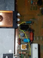
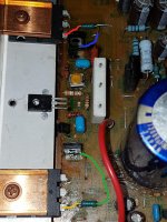
Here are results of Continuity / Resistance testing:
R766 = 328.8 ohm
Q762 base to R766 (yellow) = continuity (2.2ohm)
Q762 base to R766 (green) = 330.7 ohm
Q758 emitter to R766 (blue) = continuity (0 ohm)
Q758 emitter to R766 (red) = 328.5 ohm
Attachments
dfear, please give Molly the answer what you get with ohmmeter on emitter of Q758 and base of Q762.
It is very possible that R766 is bad.
My first quick check would be measuring resistance between Q762 and Q764 base. It should be around 330ohm.
If he can't read the value mentioned, probably R766 is burnt as said.
Mooly you are good man and patient.
It is very possible that R766 is bad.
My first quick check would be measuring resistance between Q762 and Q764 base. It should be around 330ohm.
If he can't read the value mentioned, probably R766 is burnt as said.
Mooly you are good man and patient.
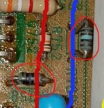
I'm struggling to make sense of the picture tbh.
Q762 is the lower left output transistor in the picture. R766 should be the resistor right next to the base.
These resistors looked frazzled as well.
Hi Mooly
I am an idiot, plain and simple. When, in post #95, I said I was testing from either Q762 or Q758 to R766, I was actually testing resistor R764. Therefore all the results in post #95 are CRAP.
Thanks for checking the photo. One of the two circled resistors is ok but the other is definitely BAD.
Results:
R758 = 99.6 ohm
R766 = 2.5 ohm
R762 = DEAD
As both R758 and R762 look frazzled, I will replace both and redo the tests I did in post #95.
No worries
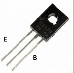
I'm also going to ask you to check (because working from pictures isn't easy) that you have the BD139 and BD140 fitted correctly. Both types have this pinout with collector in the middle.
So make sure that the emitter of each goes to the 2.2 ohm. As I say, I can't tell from the pictures. Lets be sure
Attachments
No worries
I'm also going to ask you to check (because working from pictures isn't easy) that you have the BD139 and BD140 fitted correctly. Both types have this pinout with collector in the middle.
So make sure that the emitter of each goes to the 2.2 ohm. As I say, I can't tell from the pictures. Lets be sure
Thanks for the info.
I have replaced R762 and R758 as you said they looked frazzled. One tested ok and the other was BAD.
I checked the BD139 and BD140 and they WERE the wrong way round. I have rotated each one 180deg and have redone the tests from post #81.
The results are as follows:
When the AMP is powered on the lamp on the series lamp limiter is very bright and flickers. The power led on the amp flickers too!
Voltage results:
Upper transistors:
Q762 = 739 to 797mV
Q758 = 1.423 to 1.490V
Q754 = 2.045 to 2.1V
Lower transistors:
Q764 = -701 to -744mV
Q760 = -1.385 to -1.389V
Q756 = -2.030 to -2.034V
Attachments
- Status
- This old topic is closed. If you want to reopen this topic, contact a moderator using the "Report Post" button.
- Home
- Amplifiers
- Solid State
- Marantz PM66KI amp - resistor keeps dying!