Electrically they should be fine, just alter the pin-outs to suit.
I am not quite sure what you mean?
Should I just put them into the PCB in the same orientation as marked on the board? or should i bend the pins so the pins of the MPSA devices go into the board into the correct configuration?
You absolutely must bend the leads to match the original configuration. Get this wrong and it will all go pop instantly.
Would KSA992/KSC1845 be good replacements for 2SA970/2SC2240?
They have the same pin configuration and are available from Farnell.
Thanks
I think those you mention only have a maximum current rating of 50ma vs 100ma for the others... so depending on operating conditions they may or may not be suitable.
Do you know of tany ransistors that have the same pin configuration as KSA992/KSC1845, but have a higher maximum current rating. @jaycee on this forum said the ksa/ksc pair would be ok.
P.s I have replaced the MJL, BD devices, and the burnt resistor so far. Won't power on until the third pair has been replaced.
If you are worried over these transistors then how about using these as a swap and fitting the KSA/KSC's in their place. The parts list shows these to be the same type number.
Are you saying that if I use KSA/KSC transistors for Q754 and Q756, I should also replace QN02 and QN02 with KSA/KSC devices too?
Which of the follow 4 options would be best?
1) Replace Q754 and Q756 with MPSA devices and swap the B and C legs; and NOT change QN01/02.
2) Replace Q754 and Q756 with KSA/KSC devices and NOT change QN01/02.
3) Replace Q754/756 AND QN01/02 with KSA/KSC devices.
4) Replace Q754/756 with some other transistors.
Thanks again.
The circuit shows QN01 and QN03 to be the type as Q754 and Q756 and so I'm saying that to remove any doubts on your part over fitment you should do a swap for these devices. Fit QN01 into the Q754 position and QN03 in the Q756 position.
Having done that you can then fit your MPSA devices into the vacant QN01 and QN03 slots taking care to orientate the leads correctly. These two transistors are in the protection circuit and because its all high impedance circuitry nothing bad would happen if you did get these two wrong in some way.
Having done that you can then fit your MPSA devices into the vacant QN01 and QN03 slots taking care to orientate the leads correctly. These two transistors are in the protection circuit and because its all high impedance circuitry nothing bad would happen if you did get these two wrong in some way.
Attachments
The circuit shows QN01 and QN03 to be the type as Q754 and Q756 and so I'm saying that to remove any doubts on your part over fitment you should do a swap for these devices. Fit QN01 into the Q754 position and QN03 in the Q756 position.
Having done that you can then fit your MPSA devices into the vacant QN01 and QN03 slots taking care to orientate the leads correctly. These two transistors are in the protection circuit and because its all high impedance circuitry nothing bad would happen if you did get these two wrong in some way.
Any swapping of legs necessary if I fit the MPSA devices in QN01/02?
Yes, look back to post #38. You have to bend the collector and emitter leads to suit.
I normally just push them into place and then twist the transistor slightly so that they are not shorting together. Takes seconds, no tools required")
I normally just push them into place and then twist the transistor slightly so that they are not shorting together. Takes seconds, no tools required
Attachments
Yes, look back to post #38. You have to bend the collector and emitter leads to suit.
I normally just push them into place and then twist the transistor slightly so that they are not shorting together. Takes seconds, no tools required
Hi
Crappy Q754 & Q756 removed and replaced with transistors from QN01 and QN03.
AND
Vacant QN01 and QN03 replaced with MPSA devices.
Also I replaced C752 (with good good brand cap. from RS) as it had a slight bulge.
So.... what's the next stage? Power on using the series lamp limiter?
Firstly, double check all your work and be 100% sure you have the correct devices (NPN/PNP) fitted correctly.
Next set the bias preset to its maximum resistance (so it appears in circuit as a 2k2 resistor and not as zero ohm. This will ensure the bias is at the lowest possible value.
If you are certain everything is good then power up using a bulb. No speakers attached.
Next set the bias preset to its maximum resistance (so it appears in circuit as a 2k2 resistor and not as zero ohm. This will ensure the bias is at the lowest possible value.
If you are certain everything is good then power up using a bulb. No speakers attached.
Firstly, double check all your work and be 100% sure you have the correct devices (NPN/PNP) fitted correctly.
Next set the bias preset to its maximum resistance (so it appears in circuit as a 2k2 resistor and not as zero ohm. This will ensure the bias is at the lowest possible value.
If you are certain everything is good then power up using a bulb. No speakers attached.
I have checked all replacement components are in the correct positions.
Results of checking:
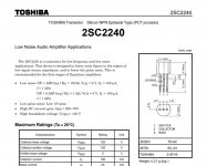
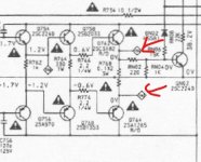
Q754 - 2SC2240
Q756 = 2SA970
Q758 = BD139
Q760 = BD140
Q762 = MJL21194
Q764 = MJL21193
QN01 = MPSA42
QN03 = MPSA92
Also:
R764 = 328.4 ohm
I have set the trimming resistor (R756) to MAX, but the max resistance on the trimmer is 1.772K ohm NOT 2.2K ohm. The min resistance is 21.9 ohm.
Does it matter that the trimming resistor's (R756) max resistance isn't the same as what is specified in the service manual?
FYI the other trimming resistor (R755) is set to: 1.062K ohm.
FYI: trimming resistor were set/tested whilst the board was unpowered and in-circuit.
Resistance values will be influenced by other circuitry around them, the 1.7k setting is the one we want.
(Two other ways of forcing a zero bias condition would be to remove R754 or simply link out C752)
All these achieve the same thing, a minimal bias state.
So all looks OK up to now... good luck, I'll look in later.
(Two other ways of forcing a zero bias condition would be to remove R754 or simply link out C752)
All these achieve the same thing, a minimal bias state.
So all looks OK up to now... good luck, I'll look in later.
Resistance values will be influenced by other circuitry around them, the 1.7k setting is the one we want.
(Two other ways of forcing a zero bias condition would be to remove R754 or simply link out C752)
All these achieve the same thing, a minimal bias state.
So all looks OK up to now... good luck, I'll look in later.
Hi Mooly
I have powered on the amp for the first time in a long time and nothing bad happened, yey!!!!
P.S. the volume was set to minimum, no speakers were connected and it was powered on via the series lamp limiter.
is the next stage to adjust the bias (R756) on the Right-channel (which was the channel being repaired)? what should the bias be adjusted to and how?
Thanks again.
David
That sounds promising.
First make sure that the DC offset at the amp output is close to zero. Assuming that's OK you can try increasing the bias.
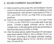
The manual is confusing as it says to connect a meter across the outer pins of the three legged 0.1 + 0.1 ohm resistor. So far so good... that means you are measuring the volt drop across what is effectively a 0.2 ohm.
It then goes on to say that you should adjust for 14 millivolts which would be equal to current of 38.9 milliamps. Well I =V/R and 0.014/0.2 equals 70 milliamps, not 38.9.
I would say don't get hung up on bias current, once you get over a couple of milliamps any audible distortion will vanish. In any case the optimum value is over 200 milliamps for this output stage and component values (don't even try that) but would cause overheating and possible thermal runaway on a commercial amp with constraints on heatsink size.
I would say aim for around 50 milliamps when its hot which means around 10 millivolts across the combined 0.2 ohms, or around 5 millivolts across each individual 0.1 ohm.
The bulb may glow a little as you alter this setting and that's fine. If all is OK and it adjusts up and down OK then turn the bias back down to zero, remove the bulb and then set it for real on full mains.
It will also be normal for the bias to change with temperature, just ensure that its not to high when the amp is really hot.
First make sure that the DC offset at the amp output is close to zero. Assuming that's OK you can try increasing the bias.
The manual is confusing as it says to connect a meter across the outer pins of the three legged 0.1 + 0.1 ohm resistor. So far so good... that means you are measuring the volt drop across what is effectively a 0.2 ohm.
It then goes on to say that you should adjust for 14 millivolts which would be equal to current of 38.9 milliamps. Well I =V/R and 0.014/0.2 equals 70 milliamps, not 38.9.
I would say don't get hung up on bias current, once you get over a couple of milliamps any audible distortion will vanish. In any case the optimum value is over 200 milliamps for this output stage and component values (don't even try that
) but would cause overheating and possible thermal runaway on a commercial amp with constraints on heatsink size.I would say aim for around 50 milliamps when its hot which means around 10 millivolts across the combined 0.2 ohms, or around 5 millivolts across each individual 0.1 ohm.
The bulb may glow a little as you alter this setting and that's fine. If all is OK and it adjusts up and down OK then turn the bias back down to zero, remove the bulb and then set it for real on full mains.
It will also be normal for the bias to change with temperature, just ensure that its not to high when the amp is really hot.
Attachments
That sounds promising.
First make sure that the DC offset at the amp output is close to zero. Assuming that's OK you can try increasing the bias.
The manual is confusing as it says to connect a meter across the outer pins of the three legged 0.1 + 0.1 ohm resistor. So far so good... that means you are measuring the volt drop across what is effectively a 0.2 ohm.
It then goes on to say that you should adjust for 14 millivolts which would be equal to current of 38.9 milliamps. Well I =V/R and 0.014/0.2 equals 70 milliamps, not 38.9.
I would say don't get hung up on bias current, once you get over a couple of milliamps any audible distortion will vanish. In any case the optimum value is over 200 milliamps for this output stage and component values (don't even try that
I would say aim for around 50 milliamps when its hot which means around 10 millivolts across the combined 0.2 ohms, or around 5 millivolts across each individual 0.1 ohm.
The bulb may glow a little as you alter this setting and that's fine. If all is OK and it adjusts up and down OK then turn the bias back down to zero, remove the bulb and then set it for real on full mains.
It will also be normal for the bias to change with temperature, just ensure that its not to high when the amp is really hot.
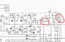
When I'm adjusting the BIAS using R768 what should I be reading on the multimeter?
I have adjusted the trimmer resistor (R768) from high to low resistance and the voltage readings on either of the outer pins read -22.60mV (MAX) or 22.54mV(MIN). I haven't been successful in measuring a 10mV difference/drop between the two outer pins; anywhere between MIN and MAX resistance. This is with the master volume set to minimum, balance set to the center position, the speakers not connected and the amp powered on via the series lamp limiter.
Am I doing anything wrong?
FYI:
The amp does power on and the resistor (R764) that used to always burn up, now doesn't.
P.S.
I have tested the other cement resistor (R767) and I only see a 3mV drop between the two outer pins.
Last edited:
You're not doing anything wrong. You should be see a tiny increase in voltage across the resistors plus the lamp should glow a little brighter. The 3 mv you see equals 15 milliamps flowing in the 0.1 ohm resistors. About right.
What you need to do is to check that the voltage across C752 increases as you turn the trimmer.
Up to now all sounds OK and the lack of bias may just be down to slight differences in the semiconductors used... which we can easily fix
I take it the - and +22mv you read are as measured from ground. If so then that's really good as well because that means the DC offset is near zero.
What you need to do is to check that the voltage across C752 increases as you turn the trimmer.
Up to now all sounds OK
and the lack of bias may just be down to slight differences in the semiconductors used... which we can easily fix I take it the - and +22mv you read are as measured from ground. If so then that's really good as well because that means the DC offset is near zero.
- Status
- This old topic is closed. If you want to reopen this topic, contact a moderator using the "Report Post" button.
- Home
- Amplifiers
- Solid State
- Marantz PM66KI amp - resistor keeps dying!