Looking closer at the currents involved and I'm going to say that the 0.47v you measure across R722 is OK and based on that, the stage is working normally.
Its possible that temperature differences of the two diodes could alter the measured volt drop more than I might have thought, particularly if Q704 is pretty warm.
The 0.001 thing is still an anomaly but if that were real then the transistor would be non functional.
Its possible that temperature differences of the two diodes could alter the measured volt drop more than I might have thought, particularly if Q704 is pretty warm.
The 0.001 thing is still an anomaly but if that were real then the transistor would be non functional.
OK, so based on the actual measurements...
D702 and D704 should have virtually identical volt drops as they are type similar devices (and probably from the same batch) and they are series connected. If they are really that far apart then something is amiss. The ISS254 is a general purpose diode and can be replaced by 1N4148 types.
As confirmation of that you can do the same voltage check on the good channel. Each diode should have similar voltage dropped across it.
That said, the values you have are workable and the voltage across R722 is in the correct ballpark. Assuming the voltages were measured accurately then 0.54v +0.74v is 1.28 volts. Subtract the B-E volt drop of approx. 0.65v and we get 0.63 volts. That would be closer to the expected value of voltage across R722... however
I would recheck those voltages and compare with the good channel. The theory is sound, its just your measured values are a little unexpected.
Something is definitely amiss there. 0.001 would be almost a short circuit which doesn;t compute with it acting as a diode in the reverse direction.
The fixed resistors seem to be OK.
Note: the left channel is the good channel.
1st RETEST (@18:53)
Right channel results:
Diode test - Q704
b-e = 0.706 (forward), 2.287 (reverse)
b-c = 0.692 (forward), 2.476 (reverse)
Voltage drop test:
R722 = 0.51 V
D702 = 0.60 V
D704 = 0.49 V
LEFT channel results:
Diode test - Q703
b-e = 0.548 (forward), 00 (reverse)
b-c = O.L (forward), O.L (reverse) -- testing cause the lamp (on the series lamp limiter) to glow brighter (increase from dim to medium), and went dim again after testing.
Voltage drop test:
R721 = 0.50 V
D701 = 0.54 V
D703 = 0.49 V
2nd RETEST (@21:03)
Right channel results:
Diode test - Q704
b-e = 0.696 (forward), O.L (reverse)
b-c = 0.691 (forward), O.L (reverse)
LEFT channel results:
Diode test - Q703
b-e = 0.700 (forward), O.L (reverse)
b-c = 0.696 (forward), O.L (reverse)
When you say the lamp is now dim, is that because you are running it with Q704 out of circuit, or has something else happened ?
If it is because Q704 is removed then that is actually a good sign and does indicate some issue with or around that transistor.
Two days ago I removed Q704 so I could test it out of circuit. Today I put it back in so I could do the in-circuit (powered on) tests. Maybe something *has* changed, but I'm not sure what. I removed and replaced Q704, but I haven't replaced R764 since it last went up in smoke. As I said, "R764 = O.L ohms".
Last edited:
That means that R764 (330R/1W) has failed.Side note:
The lamp in the series lamp limiter has gone from a medium brightness to dim or very dim.
AND R764 is no longer very hot when the amp is powered on. also R764 = O.L ohms
.
.
.
As I said, "R764 = O.L ohms".
After replacing R764, power-up on the 'bulb limiter' and measure the voltages on each leg (B, C & E) of Q758 & Q760 (I'm assuming [dangerous] that you've already checked these transistors).
N.B. You won't have much time before R764 fails again, but Q758 & Q760 are easily accessible from the underside (TO220 packages).
Power-off immediately and post the results.
Good Luck!
Addendum: Measure the above voltages with reference to 0V and don't forget to include the voltage polarity: i.e. + & -.
Last edited:
The second retest of the transistors seems OK I think we have to say they are going to be fine.
If you are holding them in your finger then its possible the resistance of your finger is enough to bring the (correct) OL reading down to the 2.2 and 2.4 you originally got. Also flux on the leads is an insulator and can give misleading results.
The voltages across R722 and R721 show the transistors and diodes are operating correctly and that approximately 7 milliamps is flowing in the resistors.
Lets try and explain the output stage to you so that you can fault find on that.
Q752 is the Vbe multiplier and its job is to provide a known volt drop across C and E.
When that voltage is sufficient to overcome the six combined base/emitter volt drops of the output transistors, the drivers and the pre drivers then the output pair begin to conduct. The manual shows +1.7 volts and -1.7 volts on Q752. That means a voltage of 3.4 volts is available to bias the whole stage and if we divide 3.4 by 6 (the number of transistors) we get 0.57 volts. That means that on average, there will be 0.57 volts across each B-E junction. That's just enough to start to turn a transistor on. Note that these numbers aren't absolute and devices vary a little, also modern manufacturing processes and doping mean modern devices vary a little compared to older one. They are always in the this zone though... up to around 700mv or so.
The difference between not conducting at all and conducting heavily occurs with a very small change in voltage across Q752.
If we short out Q752 with a bit of wire we force a zero bias condition. If you do this on the good channel you will actually find that it still all works normally... the only change will be the output transistors run cold when idling and there may be a tiny bit of detectable distortion at low volume.
So shorting this transistor is something I often recommend when fault-finding. If you do this then the output stage can not draw current in its own right.
In this state you can then build the stage up a bit at a time.
If you remove Q758 and Q760 then the whole stage should draw no current and the bulb should be dim.
The voltage on the double 0.1 ohm resistor (there may be a small indeterminate voltage because the stage is now floating) should be the same on all three leads.
There should be ZERO voltage across the 330 ohm.
With Q758 and Q760 still removed you check the voltage across R762. With the Vbe multiplier still shorted out (as mentioned above) there should be ZERO volts across this resistor as well.
So far so good")
Now we replace Q758 and Q760 but still leave the multiplier shorted.
That should give you ZERO volts across R762 and the 330 ohm. The output voltage on the 0.1 ohms should be close to zero and the amplifier should work.
When you reach that stage we look at adjusting the bias safely.
If you are holding them in your finger then its possible the resistance of your finger is enough to bring the (correct) OL reading down to the 2.2 and 2.4 you originally got. Also flux on the leads is an insulator and can give misleading results.
The voltages across R722 and R721 show the transistors and diodes are operating correctly and that approximately 7 milliamps is flowing in the resistors.
Lets try and explain the output stage to you so that you can fault find on that.
Q752 is the Vbe multiplier and its job is to provide a known volt drop across C and E.
When that voltage is sufficient to overcome the six combined base/emitter volt drops of the output transistors, the drivers and the pre drivers then the output pair begin to conduct. The manual shows +1.7 volts and -1.7 volts on Q752. That means a voltage of 3.4 volts is available to bias the whole stage and if we divide 3.4 by 6 (the number of transistors) we get 0.57 volts. That means that on average, there will be 0.57 volts across each B-E junction. That's just enough to start to turn a transistor on. Note that these numbers aren't absolute and devices vary a little, also modern manufacturing processes and doping mean modern devices vary a little compared to older one. They are always in the this zone though... up to around 700mv or so.
The difference between not conducting at all and conducting heavily occurs with a very small change in voltage across Q752.
If we short out Q752 with a bit of wire we force a zero bias condition. If you do this on the good channel you will actually find that it still all works normally... the only change will be the output transistors run cold when idling and there may be a tiny bit of detectable distortion at low volume.
So shorting this transistor is something I often recommend when fault-finding. If you do this then the output stage can not draw current in its own right.
In this state you can then build the stage up a bit at a time.
If you remove Q758 and Q760 then the whole stage should draw no current and the bulb should be dim.
The voltage on the double 0.1 ohm resistor (there may be a small indeterminate voltage because the stage is now floating) should be the same on all three leads.
There should be ZERO voltage across the 330 ohm.
With Q758 and Q760 still removed you check the voltage across R762. With the Vbe multiplier still shorted out (as mentioned above) there should be ZERO volts across this resistor as well.
So far so good
Now we replace Q758 and Q760 but still leave the multiplier shorted.
That should give you ZERO volts across R762 and the 330 ohm. The output voltage on the 0.1 ohms should be close to zero and the amplifier should work.
When you reach that stage we look at adjusting the bias safely.
Please ignore the above misinformation - the transistor packages appears to be TO126.N.B. You won't have much time before R764 fails again, but Q758 & Q760 are easily accessible from the underside (TO220 packages).
Apologies for the misinformation - there's lots of it on the Internet (along with information and disinformation).
You've stated that the (undiagnosed) problem was in the left channel, yet you introduced several 'semiconductors of unknown provenance' (fakes) into the right channel. And now there are severe issues with the right channel....I was told that one of the channels wasn't working. I was told that the left channel wasn't working...
STEP 1:
-------
as per:
Marantz PM66KI amp.
I changed Q764 Q762 Q752 Q754 Q758 Q756 Q760 QN02 QN03 anyway.
There may be broken tracks and 'collateral damage' to other semiconductors.
The unit may now be beyond economical repair.
Good Luck!
The second retest of the transistors seems OK I think we have to say they are going to be fine.
If you are holding them in your finger then its possible the resistance of your finger is enough to bring the (correct) OL reading down to the 2.2 and 2.4 you originally got. Also flux on the leads is an insulator and can give misleading results.
The voltages across R722 and R721 show the transistors and diodes are operating correctly and that approximately 7 milliamps is flowing in the resistors.
Lets try and explain the output stage to you so that you can fault find on that.
Q752 is the Vbe multiplier and its job is to provide a known volt drop across C and E.
When that voltage is sufficient to overcome the six combined base/emitter volt drops of the output transistors, the drivers and the pre drivers then the output pair begin to conduct. The manual shows +1.7 volts and -1.7 volts on Q752. That means a voltage of 3.4 volts is available to bias the whole stage and if we divide 3.4 by 6 (the number of transistors) we get 0.57 volts. That means that on average, there will be 0.57 volts across each B-E junction. That's just enough to start to turn a transistor on. Note that these numbers aren't absolute and devices vary a little, also modern manufacturing processes and doping mean modern devices vary a little compared to older one. They are always in the this zone though... up to around 700mv or so.
The difference between not conducting at all and conducting heavily occurs with a very small change in voltage across Q752.
If we short out Q752 with a bit of wire we force a zero bias condition. If you do this on the good channel you will actually find that it still all works normally... the only change will be the output transistors run cold when idling and there may be a tiny bit of detectable distortion at low volume.
Should I be shorting C-E of Q752?
Also, should I be replacing R764, before continuing with your recommended testing (in the remainder of this post).
currently R764 = O.L. ohms
<--- first part trimmed --->
So shorting this transistor is something I often recommend when fault-finding. If you do this then the output stage can not draw current in its own right.
In this state you can then build the stage up a bit at a time.
If you remove Q758 and Q760 then the whole stage should draw no current and the bulb should be dim.
The voltage on the double 0.1 ohm resistor (there may be a small indeterminate voltage because the stage is now floating) should be the same on all three leads.
There should be ZERO voltage across the 330 ohm.
With Q758 and Q760 still removed you check the voltage across R762. With the Vbe multiplier still shorted out (as mentioned above) there should be ZERO volts across this resistor as well.
So far so good
Now we replace Q758 and Q760 but still leave the multiplier shorted.
That should give you ZERO volts across R762 and the 330 ohm. The output voltage on the 0.1 ohms should be close to zero and the amplifier should work.
When you reach that stage we look at adjusting the bias safely.
06/03/19
-----------
Here are my results:
Powered on:
-------------
R764 = -25.61 V and 25.53 V
R762 = -25.12 V and 24.35 V
Check continuity:
1) Q754 emitter to R764 = NO <-- correct
2a) R764 (input) to R766 (input or output) = NC <-- correct
2b) R764 (output) to R766 (input or output) = CON <-- correct
3) Q754 emitter to R762 = YES <-- correct
4) Q754 emitter to R766 = YES <-- correct
07/03/19
-----------
Here are my results:
R774 = 2.3 ohms (close, 4.5% out, so OK)
So from testing on 6/3/19 the following conclusions have been reached:
As Q758 and Q760 have been removed the only way R764 can get voltage from is the *base* of Q762 (via R766) and current is probably being drawn by Q764 (through R774).
There is no continuity between *any two* legs of either Q760 or Q758.
Theory: most likely Q764 is faulty and/or Q762. If Q764 is replaced with the original, then R764 shouldn't glow or may glow very dim.
----------------------------------------------------
R768 = 0.3 ohms between left or right pairs.
----------------------------------------------------
Q764 - replaced with original.
R764 - not yet replaced.
Power on:
-----------
series lamp limiter bulb is *not on* or is imperceptibly dim.
R764 is cool to the the touch and doesn't move. R764 = 155.5 ohm.
Q752 still has c-e short.
Powered off:
-----------
R764 - removed. Tested = 155.5 ohm.
R764 - replaced with new.
Q752 c-e short re-instated.
Power on:
-----------
R764 = O.L ohm and voltage is 36.42V & 0V.
The series lamp limiter bulb is dim.
Powered off:
--------------
R764 = 328.8 ohm (vias need repair again!)
Q758 and Q760 replaced.
Q752 c-e short re-instated.
Power on:
-----------
R764 = 148.1 ohm - SMOKES & GLOWS.
voltage tests:
R768 output = -25.5 and climbing.
R764 = 27.83V (output), -26.60V (input).
R762 = 27.52V (input), -27.49V (output)
Questions:
Could Q760 be faulty?
Could Q758 be faulty?
Any sources of reliable and good parts?
Continuity (in-circuit):
- - - - - - - - - - - - -
Q760 b-c - NC
b-e = NC
c-e = NC
Q758 b-c = NC
b-e = NC
c-e = CON
R764 output to Q760 emitter = CON.
R764 input to Q758 emitter = CON.
From underside:
- - - - - - - - - - -
Q764 base to Q760 emitter = CON.
Q764 collector to Q760 collector = CON.
Based on your results:
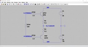
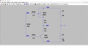
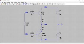
So with Q758/760 removed and R764 replaced the resistor burns when power is applied. Look at the attached diagram. This shows the configuration and theoretical voltages. The units femto and nano can be taken as no voltage (zero volts).
That means both output transistor must be faulty to burn up R764 and/or you have a physical short somewhere.
If even one output transistor were faulty and the other good then the resistor still would not burn.
Look at the second and third image. These show the upper and then the lower transistor shorted. The voltages change but there is still no current flow in the 330 ohm. The resistor sees the same voltage on each end, so no voltage across it.
So this is the first stage of fixing the amp, getting it to this condition.
I would order parts from the likes of RS, Farnell and CPC but you would be looking at modern replacements, not original type numbers.
MJL21194 and MJL21193 could be suitable output stage devices.
Try CPC, they do free delivery on orders over £8
Attachments
Based on your results:
So with Q758/760 removed and R764 replaced the resistor burns when power is applied. Look at the attached diagram. This shows the configuration and theoretical voltages. The units femto and nano can be taken as no voltage (zero volts).
No, that's not what happened, this is what did:
With a NEW Q764 and with Q758/760 removed (along with a NEW R764); the resistor burns when power is applied.
See below the quote for full explanation.
That means both output transistor must be faulty to burn up R764 and/or you have a physical short somewhere.
If even one output transistor were faulty and the other good then the resistor still would not burn.
Look at the second and third image. These show the upper and then the lower transistor shorted. The voltages change but there is still no current flow in the 330 ohm. The resistor sees the same voltage on each end, so no voltage across it.
So this is the first stage of fixing the amp, getting it to this condition.
I would order parts from the likes of RS, Farnell and CPC but you would be looking at modern replacements, not original type numbers.
MJL21194 and MJL21193 could be suitable output stage devices.
Try CPC, they do free delivery on orders over £8
I think you have either misread my notes OR I didn't explain my findings clearly enough.
I removed Q758 and Q760 As per your instructions and shorted c-e on Q752. WITHOUT replacing any other components R764 will SMOKE/GLOW/DIE.
NEXT I replaced Q764 with the original one, then powered on and tested the amp. THEN I replaced R764 with BRAND NEW one and re-tested the amp.
During the previous TWO tests the following happened:
I powered on the amp and the "series lamp limiter bulb is *not on* or is imperceptibly dim.
R764 is cool to the the touch and doesn't move".
AND with the BAD resistor in, R764 = 155.5 ohm (when amp is on); but with a BRAND NEW one in, R764 = O.L (false reading?) when the amp was on and R764 = 328.8 ohm when the amp was subsequently powered off.
It is NOW, with a GOOD resistor (R764) in, that I decided to RE-INSTATE the removed transistors (Q758 and Q760).
It is at THIS POINT, after powering on, that R764 SMOKED and GLOWED.
my notes state that I replaced the new Q760 and Q758 with the original ones on 9/2/19 and 10/2/19 (respectively).
My reckoning is that Q760 is now bad, and should be replaced. Am i correct or am I barking up the wrong tree?
Thanks for the info on where to by components and for the equivalent part numbers for Q760 and Q758.
MJL21194 and MJL21193 are Q760 and Q758 (or vice versa), correct?
OK, lets go through that bit again
That shows that both output transistors must be faulty (or there is a physical short somewhere). The only way that the resistor can get voltage across it in this configuration is via the collector/base junction in the output transistors.
So just Q764 is replaced along with the resistor.
Replacing either of the output transistors with a new one would now not burn up the resistor. So Q764 is now assumed good, and that means the collector/base junction is now blocking the current in the resistor. Thats why it doesn't smoke and burn.
Q762 still has to be faulty though because the resistor burned originally. In the post above I mentioned that both output transistors have to be faulty for that to happen.
Note... you can only test resistors when there is no external voltage across them, and no external influence from other parts fitted around them and so that means for reliable results they normally have to be checked out of circuit)
Now you move on to refit Q758/760, however Q762 is still very much suspect. This means that Q760 is now pulling current through Q762 collector/base junction, through the 330 ohm and out to the negative rail via Q760.
Q760 may or may not be faulty, either scenario would burn the resistor in this state.
Hope that makes some sense
What you really need to do is just replace the output, drivers and pre drivers.
The MJL21194/21193 are the output transistors. For the drivers (Q758/760) you could try BD139 and BD140 or MJE340 and MJE350. The pre drivers could be MPSA42 and MPSA92.
You would have to look at the physical packages and make sure these look suitable. The pinouts of the MPSA device would be different although not an issue in practice. ML21194G and ML21193G are T0264 flatpack packages.
I removed Q758 and Q760 As per your instructions and shorted c-e on Q752. WITHOUT replacing any other components R764 will SMOKE/GLOW/DIE
That shows that both output transistors must be faulty (or there is a physical short somewhere). The only way that the resistor can get voltage across it in this configuration is via the collector/base junction in the output transistors.
NEXT I replaced Q764 with the original one, then powered on and tested the amp. THEN I replaced R764 with BRAND NEW one and re-tested the amp.
So just Q764 is replaced along with the resistor.
During the previous TWO tests the following happened:
I powered on the amp and the "series lamp limiter bulb is *not on* or is imperceptibly dim.
R764 is cool to the the touch and doesn't move".
AND with the BAD resistor in, R764 = 155.5 ohm (when amp is on); but with a BRAND NEW one in, R764 = O.L (false reading?) when the amp was on and R764 = 328.8 ohm when the amp was subsequently powered off.
Replacing either of the output transistors with a new one would now not burn up the resistor. So Q764 is now assumed good, and that means the collector/base junction is now blocking the current in the resistor. Thats why it doesn't smoke and burn.
Q762 still has to be faulty though because the resistor burned originally. In the post above I mentioned that both output transistors have to be faulty for that to happen.
Note... you can only test resistors when there is no external voltage across them, and no external influence from other parts fitted around them and so that means for reliable results they normally have to be checked out of circuit)
Now you move on to refit Q758/760, however Q762 is still very much suspect. This means that Q760 is now pulling current through Q762 collector/base junction, through the 330 ohm and out to the negative rail via Q760.
Q760 may or may not be faulty, either scenario would burn the resistor in this state.
Hope that makes some sense
What you really need to do is just replace the output, drivers and pre drivers.
The MJL21194/21193 are the output transistors. For the drivers (Q758/760) you could try BD139 and BD140 or MJE340 and MJE350. The pre drivers could be MPSA42 and MPSA92.
You would have to look at the physical packages and make sure these look suitable. The pinouts of the MPSA device would be different although not an issue in practice. ML21194G and ML21193G are T0264 flatpack packages.
OK, lets go through that bit again
That shows that both output transistors must be faulty (or there is a physical short somewhere). The only way that the resistor can get voltage across it in this configuration is via the collector/base junction in the output transistors.
So just Q764 is replaced along with the resistor.
Yes, that's correct
Replacing either of the output transistors with a new one would now not burn up the resistor. So Q764 is now assumed good, and that means the collector/base junction is now blocking the current in the resistor. Thats why it doesn't smoke and burn.
Q762 still has to be faulty though because the resistor burned originally. In the post above I mentioned that both output transistors have to be faulty for that to happen.
Note... you can only test resistors when there is no external voltage across them, and no external influence from other parts fitted around them and so that means for reliable results they normally have to be checked out of circuit)
Now you move on to refit Q758/760, however Q762 is still very much suspect. This means that Q760 is now pulling current through Q762 collector/base junction, through the 330 ohm and out to the negative rail via Q760.
Q760 may or may not be faulty, either scenario would burn the resistor in this state.
Hope that makes some sense
What you really need to do is just replace the output, drivers and pre drivers.
The MJL21194/21193 are the output transistors. For the drivers (Q758/760) you could try BD139 and BD140 or MJE340 and MJE350. The pre drivers could be MPSA42 and MPSA92.
You would have to look at the physical packages and make sure these look suitable. The pinouts of the MPSA device would be different although not an issue in practice. ML21194G and ML21193G are T0264 flatpack packages.
So just to check?
-----------------
MJL21194/21193 = Q762 and Q764
MPSA42 and MPSA92 = Q754 and Q756
Also I am correct in thinking that you are saying that the 3 pairs of components (Q762/764, Q754/756, Q758/760) should all be replaced at the same time. Should I be replacing R764 at the same time too?
P.S. Thanks for all your help so far.
You only need replace the resistor if it reads obviously out of tolerance (due to overload) or is physically burnt up.
The MJL21194/3 replace Q762 and Q764 and the MPSA's Q754 and Q756.
It's really a case of just rebuilding the output stage with known good components as faults like this are very common. And remember to use the bulb tester during testing
The MJL21194/3 replace Q762 and Q764 and the MPSA's Q754 and Q756.
It's really a case of just rebuilding the output stage with known good components as faults like this are very common. And remember to use the bulb tester during testing
You only need replace the resistor if it reads obviously out of tolerance (due to overload) or is physically burnt up.
The MJL21194/3 replace Q762 and Q764 and the MPSA's Q754 and Q756.
It's really a case of just rebuilding the output stage with known good components as faults like this are very common. And remember to use the bulb tester during testing
Any recommendations for places to buy components?
I normally use RS components or Farnell. Backups are Mouser/Digikey/Rapid.
Are Cricklewood Electronics trustworthy and reliable?
RS, CPC and Farnell are all fine.. though Farnell have deteriorated somewhat since they became part of Avnet!
A lot of the parts in this amp will be obsolete and hard to get, so modern equivalents is the key. Fairchild/Onsemi do a good range of parts.
For small signal/predrivers KSA992/KSC1845 will replace 2SA970/2SC2240 very well.
For replacing the drivers MJE243/253 would be acceptable, KSC2690/KSA1220 would be better.
For the outputs, NJW0281G/NJW0302G would be a better fit than those MJL21193/4 devices... or even better, 2SC5242/2SA1962.
You only need replace the resistor if it reads obviously out of tolerance (due to overload) or is physically burnt up.
The MJL21194/3 replace Q762 and Q764 and the MPSA's Q754 and Q756.
It's really a case of just rebuilding the output stage with known good components as faults like this are very common. And remember to use the bulb tester during testing
Here is a list of he 3 pairs of components I purchased from Farnell, in order to fix the amp:
1 Transistor Polarity
NP; Collector Emitter Voltage V(br)ceo:300V; Transition Frequency ft:50MHz; Power Dissipation Pd:625mW; DC Collector Current:500mA; DC Current Gain hFE:40hFE; Transistor CaseMULTICOMP
Ordercode 1574392
Manufacturer No MPSA92
Ordered Qty 10
2 Transistor Polarity:NPN; Collector Emitter Voltage V(br)ceo:300V; Transition Frequency ft:-; Power Dissipation Pd:625mW; DC Collector Current:500mA; DC Current Gain hFE:40hFE; Transistor Case Styl
MULTICOMP
Ordercode 1574390
Manufacturer No MPSA42
Ordered Qty 10
3 Transistor Polarity:NPN; Collector Emitter Voltage V(br)ceo:250V; Transition Frequency ft:4MHz; Power Dissipation Pd:200W; DC Collector Current:16A; DC Current Gain hFE:75hFE; Transist
ON SEMICONDUCTOR
Ordercode 9555790
Manufacturer No MJL21194G
Ordered Qty 1
4 Transistor Polarity
NP; Collector Emitter Voltage V(br)ceo:250V; Transition Frequency ft:4MHz; Power Dissipation Pd:200W; DC Collector Current:16A; DC Current Gain hFE:75hFE; Transistor Case StyON SEMICONDUCTOR
Ordercode 9555781
Manufacturer No MJL21193G
Ordered Qty 1
5 Transistor Polarity:NPN; Collector Emitter Voltage V(br)ceo:80V; Transition Frequency ft:-; Power Dissipation Pd:1.25W; DC Collector Current:1.5A; DC Current Gain hFE:40hFE; Transistor Case Style
STMICROELECTRONICS
Ordercode 1084507
Manufacturer No BD139-10
Ordered Qty 5
6 Transistor Polarity
NP; Collector Emitter Voltage V(br)ceo:-80V; Transition Frequency ft:-; Power Dissipation Pd:1.25W; DC Collector Current:-1.5A; DC Current Gain hFE:250hFE; TSTMICROELECTRONICS
Ordercode 2341704
Manufacturer No BD140
Ordered Qty 5
Is every item in the list ok?
Just to check, I should be changing all 3 pairs of components at the same time, correct?
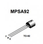
They look OK but remember to check the data sheets for the pinouts of the MPSA devices which will be different to the Japnanese 2S numbering system.
This is the MPSA pin out (same for both).
Also be sure to get the NPN and PNP types in the correct places and use the bulb tester for powering up.
This is the MPSA pin out (same for both).
Also be sure to get the NPN and PNP types in the correct places and use the bulb tester for powering up.
Attachments
Within the last 60 minutes, I've measured the voltages on my PM-66SE KI (at idle) with my 'uncalibrated' Fluke 77 multimeter as follows;Here is a list of he 3 pairs of components I purchased from Farnell, in order to fix the amp:
5 Transistor Polarity:NPN; Collector Emitter Voltage V(br)ceo:80V; Transition Frequency ft:-; Power Dissipation Pd:1.25W; DC Collector Current:1.5A; DC Current Gain hFE:40hFE; Transistor Case Style
STMICROELECTRONICS
Ordercode 1084507
Manufacturer No BD139-10
Ordered Qty 5
6 Transistor Polarity
STMICROELECTRONICS
Ordercode 2341704
Manufacturer No BD140
Ordered Qty 5
Is every item in the list ok?
242V AC - Mains voltage (unusual in N12)!
32-0-32V AC Secondary voltages.
+/-43V DC after the rectumfire.
The above transistors may not be too happy.
You may wish to consider the following (or something more modern that can handle the operating voltages);
TIP29
TIP30
Good Luck!
Last edited:
They look OK but remember to check the data sheets for the pinouts of the MPSA devices which will be different to the Japnanese 2S numbering system.
This is the MPSA pin out (same for both).
Also be sure to get the NPN and PNP types in the correct places and use the bulb tester for powering up.
Hi
long time since last post.
The pin configuration for the MPSA devices are different to the 2SA970/2SC2240 devices.
The emitter is in the same position (pin 1 on the left) BUT the base and collector are swapped.
Are the MPSA devices OK to use?
Thanks
- Status
- This old topic is closed. If you want to reopen this topic, contact a moderator using the "Report Post" button.
- Home
- Amplifiers
- Solid State
- Marantz PM66KI amp - resistor keeps dying!