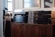
Greetings! First time posting here. I have recently put together a beautiful 90’s “mainly” Pasound system using the following equipment I have been collecting:
HCA2200II power amp,
PLD2000 pre,
DAC1100,
CDC 1500 cd changer,
In addition this set is hooked up to a vintage Pioneer turntable, Cambridge phono pre and old 70’s Jennings research contrata pedestal speakers.
I’m am very pleased it the way it sounds. It’s actually a big step up from the 70,s Marantz I am used to.
I have a question related with the amp. The power on and standby LEDs on the HCA2200II amp don’t turn on, not sure if warning leds are working either, never saw them on.
Regardless the annoyance the relays click in after a few seconds the power bottom is flipped into “on” position and the amp runs stable and sounds great.
All visible interior wiring is apparently connected.
Is this a reason of concern?
Would this be an easy fix?
Attachments
Last edited:
It works, but two status LEDs are dead?
https://www.diyaudio.com/forums/att...-parasound-hca-2200ii-inquiries-hca2200ii-pdf
At first I thought there might be a minor power supply, failed. However the plan shows these LEDs taking power from the MAIN power rail. If this failed, the whole amp would be dead.
LED power returns through mystery part T70A R1U1. I do not know what this is. Maybe an over-heat cut-out.
I do not see any problem running without the LEDs. The fault appears to be localized to the LED circuit. Living LED-less saves a part-Watt on your electric bill.
I do not know if these parts are accessible for diagnostics or repair. It looks like T70A should read zero volts to ground at normal temperature, both pins.
The LED leads should be 3V to 8V one end, 1V to 5V the other end. If they are all +70V, something "below" the LEDs is blown; if all near zero V then R144 is the likely fault.
R144 drops the main B+ to few-Volts for LEDs. It passes some current in standby, s may have many hours of use. Figuring the likely power, we have 0.6 Watts in a "1 Watt" part. A resistor's rating has to be derated for how long you want it to live. 1 actual Watt may be only 30 days. If we want to live for "years" we normally double the actual power to pick a resistor, thus 1.2 Watt part. Here the part may have been hot for 25 years, so maybe it could have been picked larger. But maybe space is cramped?
_I_ would grab a 10K 2W resistor and see if it fits at R144. The slightly higher R value slightly reduces heat. The higher W value gives hope the repair will last more than 25 years.
Definitely, this is very helpful information! Thank you very much!
I have found some info mentioning the 2w resistors. Apparently a common problem in these units as they generate heat enough to bake the circuit board bellow, and eventually become loose over time... oh well, that’s 20 years in service!
That source advised to bump the wattage rating and lift them up a bit....
It works, but two status LEDs are dead?
https://www.diyaudio.com/forums/att...-parasound-hca-2200ii-inquiries-hca2200ii-pdf
At first I thought there might be a minor power supply, failed. However the plan shows these LEDs taking power from the MAIN power rail. If this failed, the whole amp would be dead.
LED power returns through mystery part T70A R1U1. I do not know what this is. Maybe an over-heat cut-out.
I do not see any problem running without the LEDs. The fault appears to be localized to the LED circuit. Living LED-less saves a part-Watt on your electric bill.
I do not know if these parts are accessible for diagnostics or repair. It looks like T70A should read zero volts to ground at normal temperature, both pins.
The LED leads should be 3V to 8V one end, 1V to 5V the other end. If they are all +70V, something "below" the LEDs is blown; if all near zero V then R144 is the likely fault.
R144 drops the main B+ to few-Volts for LEDs. It passes some current in standby, s may have many hours of use. Figuring the likely power, we have 0.6 Watts in a "1 Watt" part. A resistor's rating has to be derated for how long you want it to live. 1 actual Watt may be only 30 days. If we want to live for "years" we normally double the actual power to pick a resistor, thus 1.2 Watt part. Here the part may have been hot for 25 years, so maybe it could have been picked larger. But maybe space is cramped?
_I_ would grab a 10K 2W resistor and see if it fits at R144. The slightly higher R value slightly reduces heat. The higher W value gives hope the repair will last more than 25 years.
Sorry for the double post, thought it didn’t go through and posted agai...
I had the chance to verify R145 in reference to ground, one side is 76vdc the other 6vdc... could the leds be blown or should I look somewhere else?
Just checked the bias setting on this power amp. Both channels were set at 10mv across emitter resistors, the service manual calls out to set it at 20mv (+-2mv), no load, after the amp is running for 1/2 hour and then readjust after it's stabilized.
I proceeded as per manual, noticed the following when powering the unit on with the voltmeter leads attached across emitter resistors:
Right channel idle current climbs up from 0mv to set value +-17.5mv
Left channel idle current climbs up to about 22mv and than comes back to +- 17.5mv, looks like it's drawing more current at startup.
Would this be a reason to be concerned?
Thanks
Direct and Normal input/output
Thanks for replies. I have sent the HCS 2200II to parasound, very helpful crew they turn it around in a few days. They replaced an open resistor on the protection circuit all other functions were running as per specification.
Another question came up, I PArasound (PL/D2000) preamp. The manual says that the Normal output should be used for amplifiers that you are not sure can protect your speakers from DC in the signal path.
Not sure what the Direct Input does. is added/removed from the audio path? The use of both is recommended for best fidelity sound.
Could you please lecture me on Direct Input and Direct Output?
Thanks
The manual says that the Normal output should be used for amplifiers that you are
not sure can protect your speakers from DC in the signal path. Not sure what the Direct Input does.
is added/removed from the audio path? The use of both is recommended for best fidelity sound.
The direct inputs bypass some switches and parts.
Direct outputs remove the polarity switching relay from the signal path.
http://www.parasound.com/pdfs/vintage/pld2000om.pdf
- Status
- This old topic is closed. If you want to reopen this topic, contact a moderator using the "Report Post" button.
- Home
- Amplifiers
- Solid State
- “New” 90’s Parasound set up - question