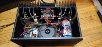
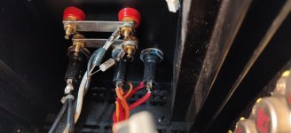
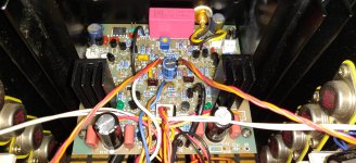
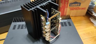
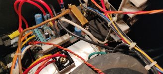
Hello everyone, first post here, I should have joined long ago! Here is my latest project, a pair of Adcom GFA565 mono blocks. I actually just finished them today after a very long and tedious rebuild. I built 100% brand new input boards with only the best components. The soft start board was rebuilt and upgraded, as well as a new metal-case hardwired bridge rectifier. I moved the zobel circuit to directly across the speaker terminals instead of on the input board and upgraded the power caps to 47,000uf. One amp had all 10 of the 2sb554 transistors open, so the entire right block had to be replaced, along with broken wires and previous shoddy repairs. I had acquired a 3rd complete amp to be used as a reference as well as for parts which helped immensely. So far they are performing outstanding, with essentially 0mv of DC and bias sitting solid at 24mv. One amp has a slightly mechanically noisy transformer, so I may swap it out if it gets worse. I have to give many thanks to Chris Hoppe as well as the old threads on this site, I couldn't have done this without that help. Any tips or suggestions are welcome! Now onto the next project..
Attachments
Wow, very nice. I have two 565's that I've owned since I purchased them new way back in the 90s.
One of them has a very slight bit of DC at the ouputs so I took them out of service about 5 years ago.
I've done a bit of repair work back years ago, and have a degree in EE, which only means that I understand a few things but means nothing for repair work.
I've collected notes and information about repairing/upgrading them for a few years, most of it from here, and need to get motivated to do them. Or find a good home for them if someone else wants to do it.
At least you've given me some inspiration to do something!!
gabo
Hey that is great that you still have those after all this time! I'm sure in the research you have done you have seen the capacitor issues that plague these amps. The only way to really repair these is a complete new input board, I would never take a gamble with just cleaning the boards. Luckily there is a plethora of information available to get these back to better than new. I didn't originally plan to go all out on these, but I am glad I did. I only took electronics shop in highschool, the rest I've learned on my own.
Yea my plan, since the input boards are known issues, was to remove that and clean/replace caps and possibly any other parts that have issues. But you say you replaced with new boards, where do you get those?
I'm hoping that reworking the input boards is all I have to do, but we'll see. I know they haven't been abused or previously repaired, so all pretty clean inside. They were working but I starting noticing a pop when I would power them on, so started looking at them. That's when I found the DC across the terminals and immediately took them out of service before they screwed up my speakers.
They've been sitting idle since, so now I drug them out of the closet and am serious about doing something with them.
Any list of substitute parts or sources would be greatly appreciated as I need to start collecting things and getting to work.
gabo
Found the source for the input boards on the "another adcom GFA 565" thread.
Which is here:
(Yet Another Adcom GFA-565 Thread
and ordered two completely assembled and tested input boards, so that should cut down on a lot of work.
I've been disassembling them and testing other areas and have ordered a few parts for things I have found. Hopefully I'll not incur the myriad of problems that are outlined in the other thread.
But at least I'm off and running on these!
gabo
Zentron, you mentioned that you "upgraded the power caps to 47,000uf"
I assume you mean the filter caps that were originally 35,000uf, 100v? The big ones mounted to the chassis.
If that is correct, where did you source those from? From the pics, it looks like they fit perfectly in the chassis. I have one of the caps that is bad, so would be nice to know where you found those.
Thanks, gabo
On my first 565, I finished the soft start board rebuild and replaced caps on the output boards.
Put the soft start board back in, with no input or output boards connected, shorted the resistor on the soft start board and slowly applied power via the variac.
So basically just powering up the power supply to check operation. As I brought up voltage, the current draw remained ok. Current draw at full voltage was about 110ma, maybe filter cap leakage? With a little bit of transformer hum, but nothing big.
The rail voltages are all good, with plus/minus 86 volts respectively. Upon power down, the filter caps discharged slowly taking about 10+ minutes to fully discharge.
This all seems to successfully test the soft start board, transformer, bridge rectifier, filter caps and their respective discharge circuits. So all good at this point. Albeit with no load.
My new and fully populated input boards from Chris Hoppe are scheduled to arrive this week. That is really going to save me a tremendous amount of time and effort. Not sure if Chris puts the zobel network on the board or not. If it's there, I'll probably remove those components as I've already purchased the parts to move that to the output terminals.
After replacing the caps on the output boards, I've done simple tests on the other components. With these tests, all the transistors and other components seem to be ok. We'll see if that holds after we get the input boards and can fully assemble.
I did reinstall the output boards, and again power up the unit. With no input board but full rail voltage applied to the output boards. No issues there and current draw remained at 110ma at full power.
When I receive the new input boards, hopefully it will be a matter of installing, doing bias adjustments, and testing to have a fully functional amp.
I can't thank this forum and all the 565 threads and participants enough. So much great info on these amps and what to do. And thanks to this thread for getting me moving on doing these! Once I finish I may have to start my Carver 1.5T and my Hafler DH-220 as I have each of these on my bench needing attention as well.
gabo
Yesterday I received my new input boards from Chris Hoppe. Very nice! In case any one else wonders, Chris does not put the zobel circuit on the board and he includes the parts to move that to the terminals. Very nice.
After installing the board on my first 565 and slowly bringing it up on the variac. Everything checked out good.
I removed the variac and the short across the soft start resistor and fired it up. Everything looked good and a quick test of the DC bias showed it sitting at 26mv.
A quick adjustment, very sensitive, set it back to 24mv. I then hooked up a source and load. It easily ran up to 100watts, where I left it for 1/2 hour or so. Then rechecked the bias and it had settled at 25mv. Due to the accuracy of my meter and the sensitivity of the adjustment, I left it there. DC voltage at the outputs was 3mv.
I then decided to run it up and see what it would do. My load resistor is actually right at 9ohms, so my power tests were to that load. Using a 100hz signal and a scope, I measure clipping right around 330watts. Let it run at 300watts for 30 minutes. She heated up a bit, but not really too much.
This one is a success. On to the 2nd unit.
Thanks again to Chris Hoppe and everyone here for all the great info.
gabo
- Status
- This old topic is closed. If you want to reopen this topic, contact a moderator using the "Report Post" button.
- Home
- Amplifiers
- Solid State
- Intro and rebuilt Adcom GFA565's