Many years ago, in fact, I had a gold voice E210 E305 series PCB circuit which imitated the board.
I also made some test boards. The result is: if DIY's golden voice, the performance is not as good as the original machine.
Even the LM3886 estimate is not comparable. So I sent the PCB made. Then? There is no more below.
Especially around 2006, the music fax X-A50 is also being imitated and DIY improved at the same time.
Comparisons show that the X-A50, the later DIY version of MX50X2, is much better than the directly engraved Golden Voice E-210 in all aspects.
So later, the similar circuit in Jin's voice did not continue DIY anymore.
In the following process, I also found some reasons for the problems.
Firstly, the circuit of the golden voice is fully symmetrical. This circuit is symmetrical in theory, but in practice, the inconsistency of the components makes it possible to apply it in practice.
The distortion of full symmetric circuit is greater than that of single-ended amplifier circuit.
For example, L series L12-2 L20.5 and music fax X-A50 distortion, is better than the golden voice, Malanz, similar structure.
Later, after a long period of research, in fact, that is to say, when you have time to study it by the way. It is found that the imitation of golden voice circuit should be made directly according to the original factory.
Not ideal, after all, DIY components are different from the original factory.
Some DIY imitations use the same type of components as the original factory, but the brand is different.
More is the use of alternative components. That is to say, no matter the model, brand, or even the parameters are completely different from the components of the factory.
But the circuit parameters are the same as those of the factory.
There are even some field effect transistors, which are directly changed into triodes, but the circuit structure is exactly the same.
This is a messy approach, but many circuits like Golden Voice use JFET MOSFET, and the model is hardly directly available.
So many DIY can't do anything, only to make a messy change, as long as the final success.
In fact, I do not object to the change, because DIY is not a manufacturer, it can not have exactly the same components. But if we make a random change, only God knows the good and bad.
This kind of DIY is in fact a universal imitation of famous machines, not limited to the golden voice. Other imitation machines are also included. This is also inevitable.
Because many components are not available, and even many of them are out of production. And some manufacturers have changed the model of components. For example, the power transistors of music fax are all MF letters.
MF stands for music fax, but as everyone knows, music fax does not produce transistors. The most important thing is to print your own trademark. We can only guess what model it is.
The end result is. Amplifiers from most imitation manufacturers. The actual performance is quite different from that of the manufacturer.
In my opinion, imitation does not need to copy the parameters of the original factory. At most, if the circuit structure remains unchanged, the application of each transistor can be appropriately based on the needs of the circuit type.
Make some adjustments.
Finally, the most important thing is to measure the amplifier. The measured data are compared with the parameters of the original plant, and then improved to achieve the same results as the original plant. It may even exceed the performance of the original machine.
This is a more practical imitation.
Without changing the circuit structure principle of the manufacturer, it is my personal imitation idea to bring the circuit performance of this structure into a better state.
Most DIYERs do not pursue performance metrics very much, and of course there may be no such condition. After all, a tester AP2722 costs hundreds of thousands of yuan.
But we can try to make it in this direction.
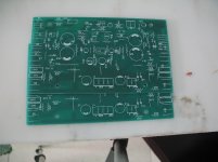
Here I start with the original version. Direct copy of the golden voice E210 PCB. I've done a lot before. They're all given away.
I also made some test boards. The result is: if DIY's golden voice, the performance is not as good as the original machine.
Even the LM3886 estimate is not comparable. So I sent the PCB made. Then? There is no more below.
Especially around 2006, the music fax X-A50 is also being imitated and DIY improved at the same time.
Comparisons show that the X-A50, the later DIY version of MX50X2, is much better than the directly engraved Golden Voice E-210 in all aspects.
So later, the similar circuit in Jin's voice did not continue DIY anymore.
In the following process, I also found some reasons for the problems.
Firstly, the circuit of the golden voice is fully symmetrical. This circuit is symmetrical in theory, but in practice, the inconsistency of the components makes it possible to apply it in practice.
The distortion of full symmetric circuit is greater than that of single-ended amplifier circuit.
For example, L series L12-2 L20.5 and music fax X-A50 distortion, is better than the golden voice, Malanz, similar structure.
Later, after a long period of research, in fact, that is to say, when you have time to study it by the way. It is found that the imitation of golden voice circuit should be made directly according to the original factory.
Not ideal, after all, DIY components are different from the original factory.
Some DIY imitations use the same type of components as the original factory, but the brand is different.
More is the use of alternative components. That is to say, no matter the model, brand, or even the parameters are completely different from the components of the factory.
But the circuit parameters are the same as those of the factory.
There are even some field effect transistors, which are directly changed into triodes, but the circuit structure is exactly the same.
This is a messy approach, but many circuits like Golden Voice use JFET MOSFET, and the model is hardly directly available.
So many DIY can't do anything, only to make a messy change, as long as the final success.
In fact, I do not object to the change, because DIY is not a manufacturer, it can not have exactly the same components. But if we make a random change, only God knows the good and bad.
This kind of DIY is in fact a universal imitation of famous machines, not limited to the golden voice. Other imitation machines are also included. This is also inevitable.
Because many components are not available, and even many of them are out of production. And some manufacturers have changed the model of components. For example, the power transistors of music fax are all MF letters.
MF stands for music fax, but as everyone knows, music fax does not produce transistors. The most important thing is to print your own trademark. We can only guess what model it is.
The end result is. Amplifiers from most imitation manufacturers. The actual performance is quite different from that of the manufacturer.
In my opinion, imitation does not need to copy the parameters of the original factory. At most, if the circuit structure remains unchanged, the application of each transistor can be appropriately based on the needs of the circuit type.
Make some adjustments.
Finally, the most important thing is to measure the amplifier. The measured data are compared with the parameters of the original plant, and then improved to achieve the same results as the original plant. It may even exceed the performance of the original machine.
This is a more practical imitation.
Without changing the circuit structure principle of the manufacturer, it is my personal imitation idea to bring the circuit performance of this structure into a better state.
Most DIYERs do not pursue performance metrics very much, and of course there may be no such condition. After all, a tester AP2722 costs hundreds of thousands of yuan.
But we can try to make it in this direction.
Here I start with the original version. Direct copy of the golden voice E210 PCB. I've done a lot before. They're all given away.
Attachments
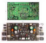
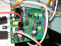
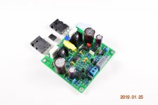
This is a circuit board improved by LJM.
Basically, the appearance doesn't show the same thing. But the selection of components and the measurement of amplifiers. That's the key to the amplifier.
Pursuing the appearance blindly is the same as the original machine. Personally, I think it is meaningless. After all, power amplifiers are used to listen to, not to see. It looks good and looks like the original machine. It's no use at all.
Attachments
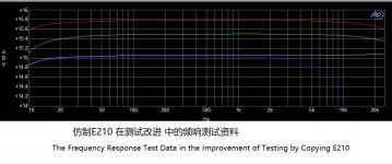
In the process of debugging, many problems will be found.
After all, this is imitation, different PCB, different components, so the same circuit structure will not be completely suitable for the best performance of the circuit.
Send some pictures of the debugging process.
Basically, each line represents a process of optimization and improvement.
Whether it is frequency response, distortion, dynamic distortion, even if the circuit is unchanged, the optimization of parameters can also improve the performance ten times, or even a hundred times.
So imagine those who download a circuit on the Internet. It can be said to be a DIY imitation of a certain machine, almost equal to substandard products.
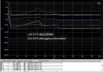
Attachments
Im wondering about servo amplifier diode D1 marked RD 8.2 , are two diodes in anti paralled coupled or only one zener 8.2 on card marked.
regard alcroner
I didn't use this 8V regulator. Take. Delete directly.
I don't think it has any practical use.
I had no problems in the test. This is my newly revised version of the photo.
Attachments
External supply of AC 36 v uses in original,its different hear and not used .
regard alcroner.
Because of driving transistors. The MOSFET is not installed together with the output transistor.
So I cancelled the 4.7R resistance. Single small radiator. It can make the transistor work stably.
In the test. The static current is affected by temperature and the amplifier works for 10 minutes. Basically, it remained stable. It will not increase or decrease.
In addition, I reduced the number of input RC.
I think the circuit diagram may be wrong, although it was not drawn by me. The brochure is provided by Golden Voice.
But I think it's still wrong, maybe deliberately.
If not changed. Then you can't hear a voice greater than 10K.
Recently bought two boards LJM E210 as in post #5.
Both are unstable and begin to overheat in 3-5 minutes after switching on (input terminals are closed).
Power supply is +-48DC.
Please advice
Yes. No mistake. E210 has a high calorific value.
Large radiators are needed.
3KG radiator is recommended.
Or turn the adjustable resistance counterclockwise.
Please advice
Compared with. L20 or L20.5, the fever is smaller. The performance is very good.

Hello.
I bought eight boards on EBAY.
Three work wrong.
Problems:
The quiescent current is 10mA and is not adjustable.
The playback is severely distorted.
If I compare this with a work board, the quiescent current is 20 mA and is adjustable.
The music playback is then ok.
Maybe you can help me??
I bought eight boards on EBAY.
Three work wrong.
Problems:
The quiescent current is 10mA and is not adjustable.
The playback is severely distorted.
If I compare this with a work board, the quiescent current is 20 mA and is adjustable.
The music playback is then ok.
Maybe you can help me??
idling current
So what idling current has to be set for E210 board?
Aliexpress for this board sayng in Section Parameters:
Quiescent current, adjust IQ TEST test 2 points voltage is 1MV, quiescent current is 13MA
Later in section Note:
● It is recommended to use a high-power tube. The voltage on the first and third pins is about 420 MV, which will rise to 600 MV after a few minutes. When adjusting, you need to measure the quiescent current at the IQ TEST test point after the amplifier works for ten minutes.
These can be replaced. It doesn't work, I think.replace 0.1ohm 5w resistors with 0.22ohm 5w, replace power transistor with 2sa1302 and 2sc3281 (copland csa 14) set trimmer for 5mv (about 23ma) swap trimmer 2k for 500ohm first.very good sound with my chario syntar 300!!!!
19435200 is actually the same thing as 13023281. All parameters are the same.
Just changed the name. 2SA1302 has been discontinued. In fact, it is replaced by 2sa1943
Generally, the finished product will be set to OK.idling current
So what idling current has to be set for E210 board?
Aliexpress for this board sayng in Section Parameters:
Quiescent current, adjust IQ TEST test 2 points voltage is 1MV, quiescent current is 13MA
Later in section Note:
● It is recommended to use a high-power tube. The voltage on the first and third pins is about 420 MV, which will rise to 600 MV after a few minutes. When adjusting, you need to measure the quiescent current at the IQ TEST test point after the amplifier works for ten minutes.
There is no need to adjust. It sounds good.
no But through the main power supply. Add 12V zener diode.Hello!
My question is: did you also power the pre-amplifier Q1-Q7 from a half-wave rectifier as in the diagram in the attachment? АС ~35V?
Supply power to the operational amplifier. E210 can set the jumper to. Post amplifier mode. Combined amplifier mode.
Ok, understood.no But through the main power supply....
P.S. The rest of the answers are probably not addressed to me
- Home
- Amplifiers
- Solid State
- Accuphase E210 modified version