I think I will try again with the cfp. The CFP just has 1 Vbe to negate. I see the
light.
OS
Pete, if I may...
")
Here is a rather successful arrangement I used in a couple of my amplifiers.
It looks like CFP at a first glance, but it's not CFP. It would be CFP if the collectors of the common-emitter transistors would be connected to the emitters of Q2, Q3.
In this arrangement, those are just the "helper" transistors with their collectors connected to the output.
This configuration is not new - Nelson Pass used it in Nakamichi PA5, PA7, and some other designs, I have just adapted the topology to my needs.
It's very stable in my amps, although my global loop gain is below 20db.
Low distortion, pretty cool distortion profile. The number of "helper" transistors may be different. No base stoppers - those will ruin the quality.
Cheers,
Val
Attachments
Hi Val,
I have also simulated this output stage before. It seems very promising and you can get very low distortion if the current in the outer transistors are set correctly.
What I fail to understand though is how to keep the outer devices from thermal runaway. The Vbe multiplier only controls the current in the inner devices. As the outer devices heat up, their idle current will increase and there is no feedback loop to control this. How did you make that work?
Just another experience:
Use equal psu steps, say 4x30V this is the best for the efficiency. All PA amplifiers are based on this solution.
Sajti
Yes , 2-1 or 3-1 ratio is what class G "guru's" say.
I got the CFP working just about like the EF steps. I see the CFP negates
itself thermally. I won't runaway.
Why not show that whole Crest amp schema. Share that inspiration.
OS
Pete, if I may...
Here is a rather successful arrangement I used in a couple of my amplifiers.
It looks like CFP at a first glance, but it's not CFP. It would be CFP if the collectors of the common-emitter transistors would be connected to the emitters of Q2, Q3.
In this arrangement, those are just the "helper" transistors with their collectors connected to the output.
This configuration is not new - Nelson Pass used it in Nakamichi PA5, PA7, and some other designs, I have just adapted the topology to my needs.
It's very stable in my amps, although my global loop gain is below 20db.
Low distortion, pretty cool distortion profile. The number of "helper" transistors may be different. No base stoppers - those will ruin the quality.
Cheers,
Val
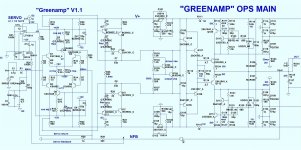
This is what I meant by "the CFP" . (below) - CFP class G steps.
I have it working way.... better than before. Must refine it (non-switching).
Almost caught back up on my LT skills + new "tricks".
You are right , the CFP ... (my stepper) goes unstable with 4.7R stoppers.
My EF3 "does not like" stoppers at either pre or driver bases. EF3 outputs
require stoppers. EF2 - stoppers everywhere !
PS - got all my EF3 hints from Bob Cordell - "troubles with triples" thread.
Really helpful - indeed. He really likes triples.
OS
OS
Attachments

What I fail to understand though is how to keep the outer devices from thermal runaway. The Vbe multiplier only controls the current in the inner devices. As the outer devices heat up, their idle current will increase and there is no feedback loop to control this. How did you make that work?
They’re underbiased in current terms by relatively huge emitter resistances so bias point are slightly affected by thermal issues. Also drive resistances have 5x nominal and controlled bias by previous stage.
Very impressed !!!
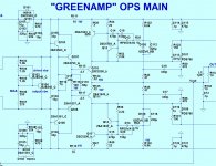
Attached is the final and .ASC + models.
I have soft switching , Ccb of Q110 and Ct of D103 can be "modeled"
with C111 and C112. This in turn allows you to "model" the tracking of
the step (attack and decay) , R118 bias and R123 to load the tracking rail
adds just a touch of forward bias without affecting the tracking voltage.
Many compromises to allow both smooth tracking and minimize class B
evil's ...
Run the sim , super !!! I like it better than the slewmaster OPS.
Have the .txt in the same folder as the .asc .
OS
Attachments
Yes , 2-1 or 3-1 ratio is what class G "guru's" say.
I read an AES paper by Jamie Angus on this topic. Basically she found that music has largely Laplacian distribution of amplitude values. Based on that one can calculate the optimum switch-points.
The first switch point is often surprisingly low. In the paper there is an example for an amplifier with 40V rails. For a single switch point it should be at 13.1V. For two switch points it should be at 8.1V and 17.3V. For three switch points 5.9V, 11.1V and 18.8V.
This is all calculated based on playing at full level (close to clipping) all the time. If you play at lower levels or the amplifier is idle some of the time, then the optimum switch points would be lower. So I think it's useful to regard these switch points as an upper bound.
She also show that with two or more switch points, class-G has potentially higher efficiency than class-D amplifiers
They’re underbiased in current terms by relatively huge emitter resistances so bias point are slightly affected by thermal issues. Also drive resistances have 5x nominal and controlled bias by previous stage.
I used the standard 0.22ohm resistors when simulating this, increasing them will make a difference. I'll try it out, thanks.
I used the standard 0.22ohm resistors when simulating this, increasing them will make a difference. I'll try it out, thanks.
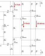
Yes, as Pavel just mentioned - high-value emitter resistors (1 ohm is good for the purpose) and low idle current for the helper transistors - 20mA per pair is more than enough. It runs very well (low distortion) even with the idle current close to zero (follower pair runs at 100+ mA anyway).
By the way, the bias spreader controls the helper transistors as well (as they are directly connected to the follower pair).
I read an AES paper by Jamie Angus on this topic. Basically she found that music has largely Laplacian distribution of amplitude values. Based on that one can calculate the optimum switch-points.
The first switch point is often surprisingly low. In the paper there is an example for an amplifier with 40V rails. For a single switch point it should be at 13.1V. For two switch points it should be at 8.1V and 17.3V. For three switch points 5.9V, 11.1V and 18.8V.
This is all calculated based on playing at full level (close to clipping) all the time. If you play at lower levels or the amplifier is idle some of the time, then the optimum switch points would be lower. So I think it's useful to regard these switch points as an upper bound.
She also show that with two or more switch points, class-G has potentially higher efficiency than class-D amplifiers
That is why chose 20V as my low rail. Big preamp trafo's would fit the bill. Most smaller PC sub toroids are 28-30V CT - perfect.
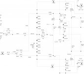
To address the " CAT of Sarcasm" , The CC1800 crest is 450/700W with
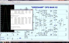
the same power supply as a typical 150W amp , and just 8 power devices. Definitely "greener". My little 4 device unit (200/400W) , should not need more than a 1U x 25cm heatsink. Crest's Vbe is now known to me (below 2). --4Vbe vs. 3 for my EF3. The step's CFP is the extra Vbe , as considered. My EF3 Vbe can be altered - it's a Vbe "multiplier" !!
Oh , the full power - crest/greenamp 400w (below 2). The 400/700W beast that will run mono on the typical DIYA 150w badger PS (and heatsink).
PS - the crest IPS is a old NE5532 op-amp .
OS
Attachments
PS - the crest IPS is a old NE5532 op-amp .
Yes, but it use the QSC solution, with common emitter output stage...
Sajti
- Status
- This old topic is closed. If you want to reopen this topic, contact a moderator using the "Report Post" button.
- Home
- Amplifiers
- Solid State
- GreenAmp ++ modulated Class G output