I was interested to read steveu's post 37 but can't figure out what post number he used to come up with the resistor numbers. Also dropping C2 requires a center tap transformer and you don't have that. ?? Also I can't read asc files since I don't simulate, so the suggestions don't mean much to me. Bootstrapping is fine, but I don't know what it is. Something about feeding drivers with output voltage through resistors, which sounds like a great way to cause oscillations. Also ostripper is one of the senior designers around here, author of the honey badger 400W amp at diysupply, but I can't read his asc file as a schematic diagram either.
MPSA06/56 are probably slower transistors than 2n2222/2907 but will be a lot less noisy at low volume. Also On semi parts are real factory controlled parts (mine came from newark), whereas central semi parts (I think you said you had) are generally whatever central can buy on the world market that is the cheapest part possible. As far as 20 k response, 1 your single speaker won't produce it unless it is 1" diameter or is a 4" with whizzer cone, and 2. most American males blew their HF ear response with firearms firecrackers or loud parties by the time they are 20. (My ears go to 14 khz tested at the factory, due to ear plug training I had in the Army and assiduous use of them. ) 3. Most pop albums don't have 10-20 khz, certainly not if they are mostly guitars & voice.
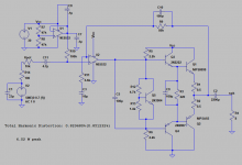
You want 5-10 ma running through TIP41/42 at idle (DC?) that is determined by the spread of the 4 diodes between the two bases of drivers. I warned you before about cutting one diode voltage down with a parallel pot with wiper connected to one end. If 2.8 v is not enough to make both output transistor turn on, add a schottky in the diode stack for another 0.3 v. Then adjust pot until idle voltage across a 0.5 ohm emitter resistor is 10 mv (5 ma).
Classic alternate way to get idle current would be to insert instead a "Vbe multiplier" instead of the 4 diodes, made of a heat sinked transistor like a BD139 or BD140, screwed to the single output transistor heat sink to collapse the voltage as it heats up. Search for Apex AX8 schematic for the simplest amp with that feature, as by contrast with Apex AX6 that I run with the diode stack on a terminal strip mounted over the heat sink. How much idle current you can get away with depends on your heat sink & heat washer: nobody uses TIP41/42 as output in class AB so I don't have a reference. But zero idle current sounds bad.
As far as limited voltage swing from this configuration, your power supply may only allow 1.5 amp or so, and that is 2.25*8 ohms or 18 watts. Your speaker was limited to 10 you said. 18 watts corresponds to a 12 v swing (rms) and I think with a 24 v supply this circuit can achieve that.
You don't have an input stage yet, I suggest a 100 ohm resistor followed by a 10k pot with one end shorted to wiper. Reason for the 100 ohm resistor you don't want to short your FM radio/cell phone when you turn the pot up to max volume trying to get your defective circuit to make some sound. Also put a 1uf or 2.2 uf or 4.7 uf capacitor in series with 100 ohms & 10k pot, some sources produce DC and the 5532 won't like that, responds assymetrically which clips one side before the power limit.
Also put 22 or 33 pf disk cap from input hot to input ground, to keep AM radio stations out of your circuit.
For emitter resistors on driver circuit, use 2.2 k as a safe way to start out. P=I*V and these are 500 mw transistors. Then you can tack solder on parallel 2.2k to lower it to 1.1 k and see if it helps anything or blows your parts. Compensation capacitor experimentation is tougher, you can tack some capacitance on with a parallel capacitor but to lower it you have to take out the old one and put in a new lower value one.
Your school lab does have a scope, right? You can check for oscillation at idle or ringing on fast slew rate inputs (square waves) with that. I don't have a working o-scope, I use an analog VOM and different blocking capacitors to see what frequency the voltage I'm seeing is actually.
MPSA06/56 are probably slower transistors than 2n2222/2907 but will be a lot less noisy at low volume. Also On semi parts are real factory controlled parts (mine came from newark), whereas central semi parts (I think you said you had) are generally whatever central can buy on the world market that is the cheapest part possible. As far as 20 k response, 1 your single speaker won't produce it unless it is 1" diameter or is a 4" with whizzer cone, and 2. most American males blew their HF ear response with firearms firecrackers or loud parties by the time they are 20. (My ears go to 14 khz tested at the factory, due to ear plug training I had in the Army and assiduous use of them. ) 3. Most pop albums don't have 10-20 khz, certainly not if they are mostly guitars & voice.
You want 5-10 ma running through TIP41/42 at idle (DC?) that is determined by the spread of the 4 diodes between the two bases of drivers. I warned you before about cutting one diode voltage down with a parallel pot with wiper connected to one end. If 2.8 v is not enough to make both output transistor turn on, add a schottky in the diode stack for another 0.3 v. Then adjust pot until idle voltage across a 0.5 ohm emitter resistor is 10 mv (5 ma).
Classic alternate way to get idle current would be to insert instead a "Vbe multiplier" instead of the 4 diodes, made of a heat sinked transistor like a BD139 or BD140, screwed to the single output transistor heat sink to collapse the voltage as it heats up. Search for Apex AX8 schematic for the simplest amp with that feature, as by contrast with Apex AX6 that I run with the diode stack on a terminal strip mounted over the heat sink. How much idle current you can get away with depends on your heat sink & heat washer: nobody uses TIP41/42 as output in class AB so I don't have a reference. But zero idle current sounds bad.
As far as limited voltage swing from this configuration, your power supply may only allow 1.5 amp or so, and that is 2.25*8 ohms or 18 watts. Your speaker was limited to 10 you said. 18 watts corresponds to a 12 v swing (rms) and I think with a 24 v supply this circuit can achieve that.
You don't have an input stage yet, I suggest a 100 ohm resistor followed by a 10k pot with one end shorted to wiper. Reason for the 100 ohm resistor you don't want to short your FM radio/cell phone when you turn the pot up to max volume trying to get your defective circuit to make some sound. Also put a 1uf or 2.2 uf or 4.7 uf capacitor in series with 100 ohms & 10k pot, some sources produce DC and the 5532 won't like that, responds assymetrically which clips one side before the power limit.
Also put 22 or 33 pf disk cap from input hot to input ground, to keep AM radio stations out of your circuit.
For emitter resistors on driver circuit, use 2.2 k as a safe way to start out. P=I*V and these are 500 mw transistors. Then you can tack solder on parallel 2.2k to lower it to 1.1 k and see if it helps anything or blows your parts. Compensation capacitor experimentation is tougher, you can tack some capacitance on with a parallel capacitor but to lower it you have to take out the old one and put in a new lower value one.
Your school lab does have a scope, right? You can check for oscillation at idle or ringing on fast slew rate inputs (square waves) with that. I don't have a working o-scope, I use an analog VOM and different blocking capacitors to see what frequency the voltage I'm seeing is actually.
Last edited:
What do you mean emitter resistors on driver circuit? Like slapping a 2.2k in between emitter of 2222 and base of MPS8099?I was interested to read steveu's post 37 but can't figure out what post number he used to come up with the resistor numbers. Also I can't read asc files since I don't simulate, so the suggestions don't mean much to me. Bootstrapping is fine, but I don't know what it is. Something about feeding drivers with output voltage through resistors, which sounds like a great way to cause oscillations. Also ostripper is one of the senior designers around here, author of the honey badger 400W amp at diysupply, but I can't read his asc file either.
MPSA06/56 are probably slower transistors than 2n2222/2907 but will be a lot less noisy at low volume. Also On semi parts are real factory controlled parts (mine came from newark), whereas central semi parts (I think you said you had) are generally whatever central can buy on the world market that is the cheapest part possible. As far as 20 k response, 1 your single speaker won't produce it unless it is 1" diameter or is a 4" with whizzer cone, and 2. most American males blew their HF ear response with firearms firecrackers or loud parties by the time they are 20. (My ears go to 14 khz tested at the factory, due to ear plug training I had in the Army and assiduous use of them. ) 3. Most pop albums don't have 10-20 khz, certainly not if they are mostly guitars & voice.
You want 5-10 ma running through TIP41/42 at idle (DC?) that is determined by the spread of the 4 diodes between the two bases of drivers. I warned you before about cutting one diode voltage down with a parallel pot with wiper connected to one end. If 2.8 v is not enough to make both output transistor turn on, add a schottky in the diode stack for another 0.3 v. Then adjust pot until idle voltage across a 0.5 ohm emitter resistor is 10 mv (5 ma).
Classic alternate way to get idle current would be to insert instead a "Vbe multiplier" instead of the 4 diodes, made of a heat sinked transistor like a BD139 or BD140, screwed to the single output transistor heat sink to collapse the voltage as it heats up. Search for Apex AX8 schematic for the simplest amp with that feature, as by contrast with Apex AX6 that I run with the diode stack on a terminal strip mounted over the heat sink. How much idle current you can get away with depends on your heat sink & heat washer: nobody uses TIP41/42 as output in class AB so I don't have a reference. But zero idle current sounds bad.
As far as limited voltage swing from this configuration, your power supply may only allow 1.5 amp or so, and that is 2.25*8 ohms or 18 watts. Your speaker was limited to 10 you said. 18 watts corresponds to a 12 v swing (rms) and I think with a 24 v supply this circuit can achieve that.
You don't have an input stage yet, I suggest a 100 ohm resistor followed by a 10k pot with one end shorted to wiper. Reason for the 100 ohm resistor you don't want to short your FM radio/cell phone when you turn the pot up to max volume trying to get your defective circuit to make some sound. Also put a 1uf or 2.2 uf or 4.7 uf capacitor in series with 100 ohms & 10k pot, some sources produce DC and the 5532 won't like that, responds assymetrically which clips one side before the power limit.
Also put 22 or 33 pf disk cap from input hot to input ground, to keep AM radio stations out of your circuit.
For emitter resistors on driver circuit, use 2.2 k as a safe way to start out. P=I*V and these are 500 mw transistors. Then you can tack solder on parallel 2.2k to lower it to 1.1 k and see if it helps anything or blows your parts. Compensation capacitor experimentation is tougher, you can tack some capacitance on with a parallel capacitor but to lower it you have to take out the old one and put in a new lower value one.
Your school lab does have a scope, right? You can check for oscillation at idle or ringing on fast slew rate inputs (square waves) with that. I don't have a working o-scope, I use an analog VOM and different blocking capacitors to see what frequency the voltage I'm seeing is actually.
I was also wondering about the MPS8099, I'm reading the datasheet here and it seems its max Ic is around 0.5 A. Is this going to be an issue if in sims I'm running up to 0.9 A through it? Or is the 0.9 A going through the emitter, and the total device wattage will be in spec?
Could I do a Vbe multiplier with either the 3904, 2222, or 41C and get away with it? I could try that instead of the three-four diode drops.
I have a scope at home which is super nice.
EDIT: Do you have some specific way you like mounting your TO-92 packages onto your heatsink? I'm considering gluing to a piece of metal? Shaping a piece of metal to wrap around top and then "grow" to add more area for more heat sink capabilities.
Last edited:
Sorry, the power limiting resistors on the driver transistors are the colector resistor R5 in post 32 (2.2k) and the invisible one on the bottom.
People use BD139 or MJE340 in TO-126 as Vbe multipliers because they have a metal flange the die is mounted on. So the heat of the heat sink communicates fast to the transistor that it is time to drop the output idle current. Heat does not move fast into TO-92 transistors. Real 2n2222 in the metal TO39 cans, you could actually clamp them to the heat sink. But plastic transistors, no heat sensing. TIP41, yes it has a heat sink but the mass is pretty high to make a Vbe multiplier out of it.
I've seen TO92 transistors clamped in metal wrappers, but nobody has sold those since about 1984. That is why you should keep your driver current down with the collector resistors.
BTW this circuit is assymetric, since the speaker is connected to one rail, instead of the center tap of the transformer. I think that makes the drive current assymetric; I'm no expert on what to do about it. This is a quick & simple circuit to make out of parts available for free from the school.
I see what you're saying. Vary those resistors to start with lower current, add another 2.2k on top or something, bam lower resistor, higher current, can see if it works better.Sorry, the power limiting resistors on the driver transistors are the colector resistor R5 in post 32 (2.2k) and the invisible one on the bottom.
People use BD139 or MJE340 in TO-126 as Vbe multipliers because they have a metal flange the die is mounted on. So the heat of the heat sink communicates fast to the transistor that it is time to drop the output idle current. Heat does not move fast into TO-92 transistors. Real 2n2222 in the metal TO39 cans, you could actually clamp them to the heat sink. But plastic transistors, no heat sensing. TIP41, yes it has a heat sink but the mass is pretty high to make a Vbe multiplier out of it.
I've seen TO92 transistors clamped in metal wrappers, but nobody has sold those since about 1984. That is why you should keep your driver current down with the collector resistors.
BTW this circuit is assymetric, since the speaker is connected to one rail, instead of the center tap of the transformer. I think that makes the drive current assymetric; I'm no expert on what to do about it. This is a quick & simple circuit to make out of parts available for free from the school.
I simulated this, seems to be okay, I could build this one I think.
As for 0.5 ohms, I was thinking about putting two 1 ohm resistors in series and therefore can share the power rating. Max power going through those in this sim is 377 mW, so two 1/4 Watts could totally share that power.
I'm a little unsure what you mean by unbalanced but ill think about it some more.
Attachments
Agh haha, you know I mean parallel haha. my bad.> for 0.5 ohms, I was thinking about putting two 1 ohm resistors in series
Check your math.
The MPS8099 MPSA55 were to replace the 2n2222 and 2n2907 drivers. Not the TIP41/42 output transistors. MPS8099 MPSA55 are also 500 mw transistors. You need TIP41/42 on a heat sink for output transistors. Or at least TIP31/32 or some TO220 package transistor. Vbe multiplier goes on the heat sink too. When you order your project board capacitors and heat sink, splurge $1 on a MJE340 or BD139 as a Vbe multiplier. Don't forget the heat sink silicon pad insulators.
Last edited:
Well that would make so much damn sense. I was getting so confused there. Alright this looks okay to me.The MPS8099 MPSA55 were to replace the 2n2222 and 2n2907 drivers. Not the TIP41/42 output transistors. MPS8099 MPSA55 are also 500 mw transistors. You need TIP41/42 on a heat sink for output transistors. Or at least TIP31/32 or some TO220 package transistor. Vbe multiplier goes on the heat sink too. When you order your project board capacitors and heat sink, splurge $1 on a MJE340 or BD139 as a Vbe multiplier. Don't forget the heat sink silicon pad insulators.
The goal of this input stage, do I want to try and make it attenuate any signals above my real range of interest, I realize that I run into losing voltage into the input for that to work? Or, do I do this approach, and compensate by adding more gain?
Attachments
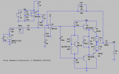
Yes, attenuating RF into the input is good. The coil you had in series with the input and the .1 uf to negative rail was not a bad idea. Just put the 33 pf cap right near the RCA or 1/8" phone jack, or on it, so the wires over to the 100 ohm resistor don't make little broadcast antennas. Put your coil & ceramic .1 between the volume pot & 5532 input, IMHO.
10x is plenty of gain from a radio earphone or cell phone earphone jack. May be a bit much. My radio can produce 7 vac on earphone. This amp can only produce 12 vac of 24 v supply. When the sound is loud weird and honky sounding, you are clipping and the gain is too high. You can tack parallel resistors over R9 to lower gain if desired when you are in checkout.
Keep your eye out for dead rocking fans and or PC's and or LED TV's on the curb on garbage day. Rocker motor of a fan makes an inductor that would stop RF cold. PCAT power supplies have an almost good enough heat sink in them. ATX supplies have a good case for this, and the fan in one boosts your cooling on the heat sink. ATX supply also sometimes has an RF blocking coil (toroid) near the AC input. LED TV's have excellent heat sinks in them. I scored a Samsung 50" last year, left the display and case for the garbage men to haul off, kept the boards. LED TV's also have cute little 10 turn coils that would make half a zobel for the output (parallel a 10 half W resistor). Also lots of 200 W Nfets.
Next most expensive part is the 100 uf non-polar capacitor on driver stack. I'd use a 33 uf polyester cap from parts-express, but the freight for you in Oregon would be too high. If your lab has 1 uf ceramic 25 v ceramic caps, put 5 of those in parallel and try that for the C9.
Last edited:
Okay, I tried simming it but it ends up looking crazy. Might just wind my own wire through some toroid and measure the L there. I think I wanna be shooting for anything withing the 10u-100uH range right?Sorry, the coil you had on the schematic previously was on the + DC line in from the +24 v switcher supply. Which is a good place for it, not on the input from the radio/cell phone.
I've been looking through this schematic attached, and looking for specialty compopnents that need to be ordered. Take a look at this BOM I created on digikey.
I already have a bunch of 2200 uF electrolytic caps, 100 uF, and anything within normal component values I can buy at school.
Digikey will allow me to sign in, but as myself, not as you. Please copy to a text file or screen capture a jpg.
If you have a magnetic toroid, about 22 turns is what the PCAT supplies use for the input filter on the AC line. Don't know how many microH that is. I used that in my mixer project that doesn't receive radio signal interference. That mixer has 50X gain on the mag phono input, so no RF in is a feat.
Remember C9 must be non-polar electrolytic or plastic film cap. Two 220 uf electrolytics minus to minus will measure 110 uf and not blow up, but I've determined by experiment that those sound a little funny. Tried to use 5600 uf + 5600 uf as a speaker cap, didn't like the sound on cymbals or top octave solo piano.
Last edited:
EDIT: that did nothing one sec.Digikey will allow me to sign in, but as myself, not as you. Please copy to a text file or screen capture a jpg.
If you have a magnetic toroid, about 22 turns is what the PCAT supplies use for the input filter on the AC line. Don't know how many microH that is. I used that in my mixer project that doesn't receive radio signal interference. That mixer has 50X gain on the mag phono input, so no RF in is a feat.
Remember C9 must be non-polar electrolytic or plastic film cap. Two 220 uf electrolytics minus to minus will measure 110 uf and not blow up, but I've determined by experiment that those sound a little funny. Tried to use 5600 uf + 5600 uf as a speaker cap, didn't like the sound on cymbals or top octave solo piano.
Digikey Part #'s:
BC1007CT-ND
445-173112-1-ND
BD13916S-ND
0.47CECT-ND
Customer Reference
C1 - signal source bypass
C9 - 100 uF ceramic across R3 (220 ohm)
BD139 - Vbe Multitplier
0.47 Ohm emitter degeneration resistors
Last edited:
Your college stockroom may be particularly well equipped, but I think you are missing:
DIP capable project board
10 k panel mount rotary pot
2k trimmer pot for vbe
10 ohm 1 w resistor for zobel network, 3 w okay if want to upgrade project to 50 w amp later.
8 pin DIP socket to protect 5532 from shorting when soldered
dual banana jack panel mount for speaker BU-P2269
dual banana plug for speaker NY8508-8
16 ga zip cord for speaker 4 '
TO-220 type silicon heat sink pads (3)
heat sink 4 cm x 10 cm x 3 cm 5 fin
1/8" panel mount stereo phono jack
1/8" stereo phono plug both ends cable (if fm radio has this jack)
3mm x-.5-8mm screws pk of 50
2.74 mm drill for heat sink for 3 mm screws
drill for 1/8" phono plug sockets (I don't have one to measure)
1/4 drill for dual banana jack above other PN may vary in size
1.5 amp continuous PTCR resettable fuse ( or higher amps if power supply will take it. )
metal box 5" x 8" x 6"
2.5 mm x 1,5 mm power socket for power supply, or whatever size fits your existing supply measure with calipers
That may not be everything but that's all for now. If your college has the parts or hardware or drills, great!
Last edited:
College has all drills which is nice.Your college stockroom may be particularly well equipped, but I think you are missing:
DIP capable project board
10 k panel mount rotary pot
2k trimmer pot for vbe
8 pin DIP socket to protect 5532 from shorting when soldered
dual banana jack panel mount for speaker BU-P2269
dual banana plug for speaker NY8508-8
16 ga zip cord for speaker 4 '
TO-220 type silicon heat sink pads (2)
heat sink 4 cm x 10 cm x 3 cm 5 fin
1/8" panel mount stereo phono jack
1/8" stereo phono plug both ends cable (if fm radio has this jack)
3mm x-.5-10mm screws
2.74 mm drill for heat sink for 3 mm screws
drill for 1/8" phono plug sockets (I don't have one to measure)
1/4 drill for dual banana jack above other PN may vary in size
1.5 amp continuous PTCR resettable fuse ( or higher amps if power supply will take it.
That may not be everything but that's all for now. If your college has the parts or hardware or drills, great!
I bought a perf board from the school, I think ittl work let me check. Let me update this post I'm gonna check digikey and put a lot of that stuff on BOM
EDIT: Yup the NE5532 totally fits in that middle section
EDIT2: can't find anything for "dual banana plug for speaker NY8508-8"
EDIT3: I have some of these for the TO220s, does this work instead of this?
EDIT4:
| Manufacturer Part Number | Digi-Key Part Number | Customer Reference | Unit Price | Extended Price | Description |
| K330J15C0GF5TL2 | BC1007CT-ND | C1 - signal source bypass | 0.26 | $0.26 | CAP CER 33PF 50V C0G/NP0 RADIAL |
| FG11X5R0J107MRT06 | 445-173112-1-ND | C9 - 100 uF ceramic across R3 (220 ohm) | 1.01 | $1.01 | CAP CER 100UF 6.3V X5R RADIAL |
| BD13916S | BD13916S-ND | BD139 - Vbe Multitplier | 0.5 | $0.50 | TRANS NPN 80V 1.5A TO-126 |
| NKN200JT-73-0R47 | 0.47CECT-ND | 0.47 Ohm emitter degeneration resistors | 0.71 | $0.71 | RES 0.47 OHM 2W 5% AXIAL |
| 3296W-1-202LF | 3296W-202LF-ND | Vbe multiplier 2k trimmer pot | 2.41 | $2.41 | TRIMMER 2K OHM 0.5W PC PIN TOP |
| 3310R-125-103L | 3310R-125-103L-ND | 10k pot | 2.74 | $2.74 | POT 10K OHM 1/4W PLASTIC LINEAR |
| A 08-LC-TT | AE9986-ND | 8 PIN DIP socket for NE5532 | 0.18 | $0.18 | CONN IC DIP SOCKET 8POS TIN |
| BU-P2269 | 314-1204-ND | Banana jack panel mount for speaker | 3.73 | $3.73 | CONN DBL BANANA JACK TURRET |
| 0ZRE0150FF1A | 507-2079-ND | Radial Reset 1.5 A fuse | 0.89 | $0.89 | PTC RESET FUSE 240V 1.5A RADIAL |
| 55PC0811-16-9CS2502 | 55PC0811-16-9CS2502-05-ND | 16 Gauge 5' Wire | 2.205 | $4.41 | HOOK-UP DUAL WALL STRND 16AWG 5' |
Last edited:
Looks like your getting the idea. I hope you can find a metal box like a recipe file at a charity resale shop or an old PC power supply or something. I forgot to list the 2.74 mm tap for putting the screw in the heat sink. If they stock something around there, buy it. the table was vague as to whether it was 2.74, 2.75, or 2.77. My porta-book from home depot says 2.5 mm but I don't think I trust that. If you havn't pushed the buy button yet, you can probably salvage the zip cord for the speaker from an old appliance - fan or something.
Radio signal source, I use a cheap tape player I fished out of the trash @ work. I wired around the defective volume pot with a 6.8 k resistor.
Have fun. It is 8 deg F here today, not going to my volunteer job. My church just turned into a homeless shelter I saw on the news. I just burned the transformer on my LM1875 stereo project, will have to order one then put it away to clear the bench.
Last edited:
Wow, it's a beautiful sunny day here, albeit a little cold. But you guys must be freezing, I hope you guys will stay warm.Looks like your getting the idea. I hope you can find a metal box like a recipe file at a charity resale shop or an old PC power supply or something. I forgot to list the 2.74 mm tap for putting the screw in the heat sink. If they stock something around there, buy it. the table was vague as to whether it was 2.74, 2.75, or 2.77. My porta-book from home depot says 2.5 mm but I don't think I trust that. If you havn't pushed the buy button yet, you can probably salvage the zip cord for the speaker from an old appliance - fan or something.
Radio signal source, I use a cheap tape player I fished out of the trash @ work. I wired around the defective volume pot with a 6.8 k resistor.
Have fun. It is 8 deg F here today, not going to my volunteer job. My church just turned into a homeless shelter I saw on the news. I just burned the transformer on my LM1875 stereo project, will have to order one then put it away to clear the bench.
So something I'm a little confused about with the main hear sink. Do I put my output transistors towards the side, and then bend them down/over to be drilled in to the heat sink? I'm going to look up some images to get a better idea, but do you happen to have a solid reference to a configuration of what size / orientation the heat sink is supposed to be, and how you fit it near / on the board?
Edit: something like any of these?
I see how they're bent down and screwed in. Or placed at the end still standing up, adjacent to the heatsink. Am I looking for something like one of these, where I can set the board kind of "resting in the middle", and the output transistors can be hooked to each side?
EDIT2: Theres a big metal scrap box at school, I think I'll look through that and potentially make my own if I find something good.
Last edited:
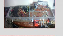
Here is my LM1875 board with the heat sink mounted to the board and the IC's screwed on it. I should have turned the legs down and drilled holes through the board for the 5 leads, but with 5 of them I didn't think I could bend them that far without breaking them. Doesn't oscillate at gain 10, I think I got away with having .1 caps 3" away from power leads. The heat sink has legs on the bottom, with a wired soldered between them on each end under the NEMA CE board.
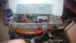
Second picture is the amp board flipped down inside the case. There is a 3rd way, flipped over screwed to the angle bracket shown on the front, so I can adjust the wiring without the board flopping around. I have since added a fan to the left of the RF bulkhead blowing on the heatsink, after moving the mesh bulkhead right.
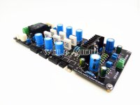
After is an e-bay amp sold without heat sink. Obviously the transistors are on the near edge with the heat sink about 8" x 8" underneath the board. So transistor leads are bent up 90 deg. The heat sink you see is the driver IC, a lme49810.
Most conventional amps have the output transistor on back edge pointing up, with heat sink vertical to the flat board. Screwing the board to the heatsink so the transistor leads don't carry the shock of dropping the amp, is a trick. You're going to have trouble with that since your project board doesn't have mount holes on it for brackets. I suggest putting the transistors on the heat sink, mounting it to the metal case, and run stranded wires from the output transistors to the project board. Make sure the Vbe leads, which are an input, are well separated from the OT leads, which are an output. Else Oscillation could occur.
Second picture is the amp board flipped down inside the case. There is a 3rd way, flipped over screwed to the angle bracket shown on the front, so I can adjust the wiring without the board flopping around. I have since added a fan to the left of the RF bulkhead blowing on the heatsink, after moving the mesh bulkhead right.
After is an e-bay amp sold without heat sink. Obviously the transistors are on the near edge with the heat sink about 8" x 8" underneath the board. So transistor leads are bent up 90 deg. The heat sink you see is the driver IC, a lme49810.
Most conventional amps have the output transistor on back edge pointing up, with heat sink vertical to the flat board. Screwing the board to the heatsink so the transistor leads don't carry the shock of dropping the amp, is a trick. You're going to have trouble with that since your project board doesn't have mount holes on it for brackets. I suggest putting the transistors on the heat sink, mounting it to the metal case, and run stranded wires from the output transistors to the project board. Make sure the Vbe leads, which are an input, are well separated from the OT leads, which are an output. Else Oscillation could occur.
Attachments
Last edited:
Okay. I will take a look at the what is at school and then if I can't find anything good, I'll add a heatsink to the digikey order. No, I have not bought anything yet from digikey. The school also sells wire, I'm going to look and see if they sell 16 gauge.Here is my LM1875 board with the heat sink mounted to the board and the IC's screwed on it. I should have turned the legs down and drilled holes through the board for the 5 leads, but with 5 of them I didn't think I could bend them that far without breaking them. Doesn't oscillate at gain 10, I think I got away with having .1 caps 3" away from power leads. The heat sink has legs on the bottom, with a wired soldered between them on each end under the NEMA CE board.
Second picture is the amp board flipped down inside the case. There is a 3rd way, flipped over screwed to the angle bracket shown on the front, so I can adjust the wiring without the board flopping around. I have since added a fan to the left of the RF bulkhead blowing on the heatsink, after moving the mesh bulkhead right.
After is an e-bay amp sold without heat sink. Obviously the transistors are on the near edge with the heat sink about 8" x 8" underneath the board. So transistor leads are bent up 90 deg. The heat sink you see is the driver IC, a lme49810.
Most conventional amps have the output transistor on back edge pointing up, with heat sink vertical to the flat board. Screwing the board to the heatsink so the transistor leads don't carry the shock of dropping the amp, is a trick. You're going to have trouble with that since your project board doesn't have mount holes on it for brackets. I suggest putting the transistors on the heat sink, mounting it to the metal case, and run stranded wires from the output transistors to the project board. Make sure the Vbe leads, which are an input, are well separated from the OT leads, which are an output. Else Oscillation could occur.
- Status
- This old topic is closed. If you want to reopen this topic, contact a moderator using the "Report Post" button.
- Home
- Amplifiers
- Solid State
- DIY Amp Design Critique