Hello, All --
At present, I have been working on a Customer's Akai AM-U61 Amplifier.
This device came to me and had been previously been worked on by another Tech, apparently without much success.
The Amp has had a recent history of blowing up the STK1080ii Output Devices.
After removing the suspect STKs from the board, I decided to then check everything for correct Component Values to ascertain what had been done in the past.
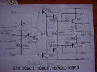
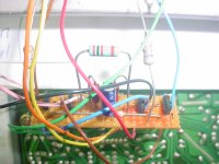
Firsty, I found that the Protection Zener Diode named as D23 was Short Circuited in both channels, no suprises here. Looking Further, I found that One of the NPN Driver Devices, TR10, (2SC2704) in one channel was suspect with a very low B to E Voltage drop, so I replaced it with the same type. To Fool the Va Stage into thinking that the STKs were in place, I made up a small Pcb with some resistors and a Darlington Transistor to take the place of the Input Stage of the STK, in each channel.
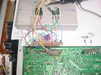
After Powering it all up off of my Variac, I increased the Mains Voltage to the correct value and proceeded to do measurements with Meter and Oscilloscope. Everything looked pretty good, so I then mounted one of the Original STK devices on an outboard heatsink and connected it to the motherboard.
Powered her up again on the Variac: Lo and behold, all voltages were almost exactly what the Akai Manual showed. No Sign of Instability at all. Did a Load Check into a Resistor Stack at 1Khz and all looked good.
Then: Inserted a New STK1080ii into the other Channel, and did the same Power up.
As soon as the Speaker Protection Relay closed, The Inner Loop between the
Va Stage output and the input Terminals of the STK went absolutely unstable, looked like bad noise on the scope. No sign of this anywhere else in the circuit, from the preamp stage through to the input of the Final Va stage was clean, even the STK Output Terminal was stable.
There is talk of Counterfeit STK Devices; how is it that the Original STK Device sets up fine, and Yet the New Device is like this? Maybe it is because
the New/current STKs are ALL Counterfeit?
I proved this by swapping the Output STKs between channels; the Fault followed the New One.
Is there any Way I can tame this?
Sorry to go on, but when people are trying to help, it pays to try and be accurate.
I will have a go to post the Circuit Schematic and Scope results.
Thanks in Advance --
At present, I have been working on a Customer's Akai AM-U61 Amplifier.
This device came to me and had been previously been worked on by another Tech, apparently without much success.
The Amp has had a recent history of blowing up the STK1080ii Output Devices.
After removing the suspect STKs from the board, I decided to then check everything for correct Component Values to ascertain what had been done in the past.
Firsty, I found that the Protection Zener Diode named as D23 was Short Circuited in both channels, no suprises here. Looking Further, I found that One of the NPN Driver Devices, TR10, (2SC2704) in one channel was suspect with a very low B to E Voltage drop, so I replaced it with the same type. To Fool the Va Stage into thinking that the STKs were in place, I made up a small Pcb with some resistors and a Darlington Transistor to take the place of the Input Stage of the STK, in each channel.
After Powering it all up off of my Variac, I increased the Mains Voltage to the correct value and proceeded to do measurements with Meter and Oscilloscope. Everything looked pretty good, so I then mounted one of the Original STK devices on an outboard heatsink and connected it to the motherboard.
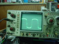
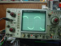
Powered her up again on the Variac: Lo and behold, all voltages were almost exactly what the Akai Manual showed. No Sign of Instability at all. Did a Load Check into a Resistor Stack at 1Khz and all looked good.
Then: Inserted a New STK1080ii into the other Channel, and did the same Power up.
As soon as the Speaker Protection Relay closed, The Inner Loop between the
Va Stage output and the input Terminals of the STK went absolutely unstable, looked like bad noise on the scope. No sign of this anywhere else in the circuit, from the preamp stage through to the input of the Final Va stage was clean, even the STK Output Terminal was stable.
There is talk of Counterfeit STK Devices; how is it that the Original STK Device sets up fine, and Yet the New Device is like this? Maybe it is because
the New/current STKs are ALL Counterfeit?
I proved this by swapping the Output STKs between channels; the Fault followed the New One.
Is there any Way I can tame this?
Sorry to go on, but when people are trying to help, it pays to try and be accurate.
I will have a go to post the Circuit Schematic and Scope results.
Thanks in Advance --
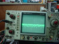
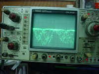
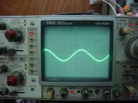
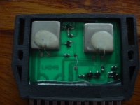
This is the Only STK1080ii Device Currently Available, and this is the Device which has the Noise/oscillation? problem when connected in the Akai Circuit.
When compared to the other, makes one wonder 'What's going on here?'
When compared to the other, makes one wonder 'What's going on here?'
Attachments
Its very hard to say what is going but you mustn't lose sight of the fact that you have confirmed that the fault follows the 'new' modules wheras the old original one appears to work.
D23 short circuit. Either there has been a 'local' problem within the STK that has killed the Zener or the fault has allowed excess current to flow through the Zener and via (at least) D2 and through TR10.
Could that explain the suspect TR10?
All that you describe does sound like there is some major difference in the modules affecting stability.
You could try a small cap across D23, something like 1uF or 10uF and also try tweaking C19 to see if it changes things. C23 and C24 could be worth tweaking as well (one a 10pF and one a 100pF ???).
Its all trial and error I'm afraid but it sounds like the bottom line is that the modules are causing the problem.
We mustn't forget that Sanyo, the only (!) manufacturer of these thick film hybrid modules, had to close it's semiconductor division in 2004 after the Chuetsu earthquake, which ruined their semiconductor plant almost completely. So it has to be assumed that any of these devices that is being marketed as from new production is conterfeit.
Sad but true .
.
Best regards!
Sad but true
.Best regards!
Hello
Thanks so much for the help. Unfortunately Trying Capacitance across D23 does not alter anything. This effect Seems to be Power Supply Voltage sensitive. The Instability/noise problem only seems to be only in the inner loop between the Outputs of TR9 -TR10 and the Input Terminals of the STK.
I discovered a Circuit Error in the Akai Drawing for the AM-U61.
The Emitter of TR10 is Connected to the Collectors of TR6, and TR8, NOT the Collector of TR12.
The Collector of TR12 is connected to the Emitter of TR13 and the Junctions of C20, and R52.
The Drawing of the AM-U61 is A Misprint, and the Akai Drawing of the similar AM-U41 is correct in this instance, but of course the AM-U41 lacks the two earlier TR5 and TR6 Devices.
I am looking at Constructing a Replacement for the STK1080. I have done a lot of research into the layout/construction of both the Original and Newer
currently availalable STK Devices, and am convinced that I can engineer a
Discrete Replacement using currently available Bi-polar devices. After all, it looks like only a Double Darlington Amp driving an ordinary Bi-polar Output Stage with a complementary pair of Output Devices. I can do this on a small Pcb, and mount the output devices onto the original heatsink.
I have already made up a trial board to test and check all voltages and currents.
I am about to mount the Output Devices and test run it from the existing circuitry of the AM-U61. It will be interesting to see what happens.
I will keep You informed on progress, because this could help a lot of Techs with a similar problem.
Hello, All
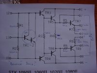
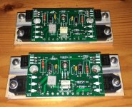
Well, Progress! I constructed a small Veroboard circuit for which I have posted the schematic of. For the Devices, I used pulls from a Yamaha RX-V740 (which I am dismantling). For the front end I used an MPS-A14 Darlington Device, which is a replacement for the 1M SMD Device used in the STK. For the other preamp/driver devices, I used The pulled 2SC4614, and 2SA1770 which are complements to each
other. The Output Devices I used were also pulls and are 2SC4468 and 2SA1695, also complements. After Checking everything carefully, I Powered it up on the Variac and watched as many voltages as I could, all looked good, so I raised the AC Input Voltage to the correct level, and proceeded to take measurements with meter and scope.
No sign of any instability, and the rest of the circuit voltages closely matched what Akai had listed in the AM-U61 schematic. I noted that The Quiescent Current started off at around 30 Ma and gradually increased as the heatsink warmed up; I had not mounted that Input Darlington on the Heatsink, and as I warmed it up, I noted that the IQ immediately started dropping, so that will be a thing I will have to do before I start to load her up and test the Output Power. I see that many Amps of about this power seem to have IQs between 20 and 50 MA, which can be adjusted by altering the value of those R1 or R2 Resistors in the Schematic. Next Thing is to draw up and etch a suitable Pcb, which only needs to be small, but at least the proof of concept seems to be okay.
What sort of IQ would You suggest that I run this at?
Thanks so much to all that have helped!
STK 1080 Replacement
https://www.diyaudio.com/forums/att...4813340&stc=1&d=1549092481&stc=1&d=1549092481
https://www.diyaudio.com/forums/att...4813340&stc=1&d=1549092481&stc=1&d=1549092481
Attachments
For the values you have in the pdf I'd say just over 100ma would be ideal but that may be considerably more than might be advisable given the heatsinking. As always these things are a compromise. The figure of 100ma is based on the comprehensive work done by Doug Self where optimal bias current is a function of Re.
In practice anything over a couple of milliamps will render the distortion totally inaudible and a figure of 30ma or so sounds more reasonable. You also have to be sure the Vbe multiplier tracks the temperature well if you want to push things. The last thing you want is thermal runaway as it heats up.
Good work though
FYI, I have designed a STK-0050 pcb, made it available free of charge for you to buy your own pcb. I have a link to the Mouser BOM for parts. Someone has made these available on eBay which includes the pcb and an Al heatsink.
It was originally designed for a Pioneer SX-780, but others have been using them to fix other amps like some Fishers' and others.
It was originally designed for a Pioneer SX-780, but others have been using them to fix other amps like some Fishers' and others.
Attachments
Good Morning All--
That looks like a nice layout of your Pcb; I am looking to do something similar for this STK 1080ii replacement, but am considering one-sided at the moment.
After dismantling several of the older and newer STK1080ii devices, I was able to make an average of the component values they used to come up with a working circuit. The Problem is that these newer STK Devices just do not work properly in the Akai AM-U61 as I have posted before, and I just can't seem to tame the problem; whereas the circuit that I just built up and temporarily fitted seems to be stable with all the correct Akai
Schematic Voltages. Also, I found yet another Error in the Akai AM-U761 Schematic;
The Collector Voltage of that TR10 Driver Transistor is actually running at Minus 4.3 Volts, the exact opposite of the Plus 4.3v Collector Voltage of TR9, which you might expect. But the Akai Drawing shows Zero point 4? -- Interesting.
To Continue:
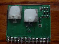
While measuring those dismantled STK 1080ii Devices, I was unable to find any real resistance in those Emitter Resistors marked as R7 and R8. There is just 2 copper tracks, which seem to measure between 0.01 and 0.02 Ohms on my Low R checker.
So in my mockup circuit, I used Point 22 Ohms in order to protect things a bit more.
What would You suggest I use in the final build?
Once again, Thanks to all for help thus far --
That looks like a nice layout of your Pcb; I am looking to do something similar for this STK 1080ii replacement, but am considering one-sided at the moment.
After dismantling several of the older and newer STK1080ii devices, I was able to make an average of the component values they used to come up with a working circuit. The Problem is that these newer STK Devices just do not work properly in the Akai AM-U61 as I have posted before, and I just can't seem to tame the problem; whereas the circuit that I just built up and temporarily fitted seems to be stable with all the correct Akai
Schematic Voltages. Also, I found yet another Error in the Akai AM-U761 Schematic;
The Collector Voltage of that TR10 Driver Transistor is actually running at Minus 4.3 Volts, the exact opposite of the Plus 4.3v Collector Voltage of TR9, which you might expect. But the Akai Drawing shows Zero point 4? -- Interesting.
To Continue:
While measuring those dismantled STK 1080ii Devices, I was unable to find any real resistance in those Emitter Resistors marked as R7 and R8. There is just 2 copper tracks, which seem to measure between 0.01 and 0.02 Ohms on my Low R checker.
So in my mockup circuit, I used Point 22 Ohms in order to protect things a bit more.
What would You suggest I use in the final build?
Once again, Thanks to all for help thus far --
Hi Mooly Thanks again --
Yes, looking at several Power Amp circuits by different manufacturers shows exactly that, .22 Ohms.
I wonder how Sanyo? and others who make these STK devices get away with it -- maybe this is the cause of some of the apparent STK unreliability that you read about?
Also, in this Akai Circuit (and probably others) the Voltage across these resistors is monitored by the Overdrive Limiting devices TR14 and TR15; so, how are they supposed to work properly when fed with such a low voltage which is developed across only .02 of an ohm? I guess I will have to look at this part of the circuit when I go to check the performance once I get that Vbe multiplier mounted to the heatsink.
I am also going to reconnect that older STK back into the circuit to measure the IQ, as I had not done that before; be interesting to see what IQ Akai ran that at.
Thanks for all!
0.02 ohm couldn't work at all as a sensing resistor, at least not just by using simple transistor circuitry. These type of resistors are often some kind of thick film type deposited onto the PCB but I can't really make anything out from the pictures and ss far as I know these types don't fail by going low in value.
Hard to say what is going on with these.
Hard to say what is going on with these.
Hi Mooly
Yes, I agree; if You look at the dismantled unit's board, in both cases, there are only Copper Tracks less than an inch long. All of the STKs I have here (both dismantled and new) measure that .02 Ohm, or less, so like You, I can't see how any protection or signal limiting can work. Maybe in the very original STK there were resistors? That is why I queried what R Values to use there. I could send You closeups if you like --
Once Again, Thanks So Much for all --
- Home
- Amplifiers
- Solid State
- STK1080ii Devices