Hi bob I read your book and I have few questions regarding driving 8 pairs of MJL21194/93. At +/-80V The application is that I have currently made an amplifier single drivers with 2sc5171 driving 6 pairs of 2sc5949 and eventually figured out that the current gain is not sufficient to drive the OPS properly. Now instead of using 2sc5171 Im thinking of using 5 pairs of MJE15032/33 or drive the 6 pairs of 2sc5949, 2sa2121 but to my surprise even with very little input less than 1V the amplifier is showing clipping on the clip indicator LED at +/-80V supply and amp gain being 29db. Im assuming the current from VAS is not sufficient to drive the OPS with ease. Now I would like to drive the subwoofer with super authority at its deepest frequencies. Im now considering using Triple EF and now would that solve the problem?
I always use to feel the sloppy bass coming out and have just excursions but no slam in bass. I believe using 8 pairs of MJL21194/93 with one pair of 2sc5949 2sa2121 as drivers and then use 2sc5171 1930 as predrivers would solve the problem?
I always use to feel the sloppy bass coming out and have just excursions but no slam in bass. I believe using 8 pairs of MJL21194/93 with one pair of 2sc5949 2sa2121 as drivers and then use 2sc5171 1930 as predrivers would solve the problem?
An amp with ±80 V supply rails, and six pairs of output transistors, justifies the purchase of an oscilloscope for debugging and testing. A scope will let you quickly discover which stage clips first: input stage, voltage amplifier stage, driver stage, or output stage? Then you can post photos of your scope traces when asking folks for their opinions and advice.
Hi bob I read your book and I have few questions regarding driving 8 pairs of MJL21194/93. At +/-80V The application is that I have currently made an amplifier single drivers with 2sc5171 driving 6 pairs of 2sc5949 and eventually figured out that the current gain is not sufficient to drive the OPS properly. Now instead of using 2sc5171 Im thinking of using 5 pairs of MJE15032/33 or drive the 6 pairs of 2sc5949, 2sa2121 but to my surprise even with very little input less than 1V the amplifier is showing clipping on the clip indicator LED at +/-80V supply and amp gain being 29db. Im assuming the current from VAS is not sufficient to drive the OPS with ease. Now I would like to drive the subwoofer with super authority at its deepest frequencies. Im now considering using Triple EF and now would that solve the problem?
I always use to feel the sloppy bass coming out and have just excursions but no slam in bass. I believe using 8 pairs of MJL21194/93 with one pair of 2sc5949 2sa2121 as drivers and then use 2sc5171 1930 as predrivers would solve the problem?
Do you have experience building and testing smaller amplifiers? 6 or 8 pairs and an 80V supply is a big amplifier and can be a challenge. For example, have you built something like a 2-pair amplifier with 50-60V rails?
As you know, I am a fan of output triples, and believe that there is just not enough current gain in a 2 EF output stage to make a really good amplifier. This is even more important if you are driving 8 triples to get lots of watts and output current. Let's say you are driving a 4 ohm load and your amplifier can deliver 64 V peak into that load, after supply sag and headroom are considered at that high power. That is 16A peak into the load. That comes to 512 W average power. With a 2 EF output stage with minim current gains of 50 and 20 in the drivers and output transistors, respectively, you have output stage current gain of only 1000 and very nonlinear. You would need at least 16 mA peak from the VAS to drive it.
For that big an amplifier, use something like TO126 VAS, TO220 pre-drivers, TO264 drivers and TO 264 outputs. At that power level, it is appropriate to use output-size transistors for the drivers. Always beware of the SOA needs of the drivers, especially considering fault conditions. Use a power transistor like the 2sc3503 for the driver, as it is faster than the MJL21194/93. Maybe for the power transistors as well.
Simulate the heck out of the amplifier before you build it.
In my view, amplifying on what Mark said, a scope is a virtual necessity if you are building a power amplifier. If you don't want to spend a lot of money on a scope, get a modest cost PC-based scope OR a vintage TEK scope from Ebay that works. Something like a TEK465 or 475 would do. You need to have eyes!
Merry Christmas,
Bob
but usually is that above triple configuration good enough?An amp with ±80 V supply rails, and six pairs of output transistors, justifies the purchase of an oscilloscope for debugging and testing. A scope will let you quickly discover which stage clips first: input stage, voltage amplifier stage, driver stage, or output stage? Then you can post photos of your scope traces when asking folks for their opinions and advice.
I do have the CRO, Function Gen, Variac but not THD analyzer. Ill check it but in general is that above config of driving multiple output transistors good enough?
Hi Bob,
Thank you very much for the reply. Yes I have built the amps with 2 3 and 5 pairs at 50, 70 and 85V but in above cases I have used everywhere as single 5171 and 1930 as drivers which was actually a big mistake and the day when I found that the sub wasnt getting slam I was thinking that it could be a impedance matching of the amp at the input hence using a low output imp preamp and eventually that was sounding relatively better but still it didnt had that slam and when I acoustically measured the sub the rolloff was relatively faster as the frequency was getting lower. I couldnt understand. Checked with labgruppen and it was awesome i realised that something was wrong double checking the heatsink temperatures and found that the heatsink was just running warm even at clipping levels. The sound was better with a lateral mosfet amp. I couldnt understand at first and then realized that is the ouput stage not getting enough drive current to take full control and after seeing the datasheets of 5171 to my surprise the output current is hardly about 0.2Amp on the continuous output scale ( I do consider DC is not always happens as the signal is music but I see some bass notes are prolonged in duration even though we take 50% of duty cycle or less of a sinewave ). I read your book and there you have mentioned about considering the design to be at 2ohm load at worst as well as back emf problem makes it even more harder to drive. That made the conclusion that the current drive wasnt sufficient. Im working on the newer version on the PCB with 5 output pairs and using same as drivers and using 2sc5171 and 1930 as pre drivers. I will test on my existing 5 pair board and let know the result.
Bob you have mentioned in the above post that 2sc3503 for the driver? or VAS driver. Im thinking the following all together
2sc3503/1381 VAS output
2sc5171/1930 Pre drivers
2sc5949/2121 drivers
MJL21194/93 output.
I have a doubt what if I use 15 pairs of IRFP240? can one 2sc5949 drive 15 pairs of IRFP240/9240?
Hi Bob I have a question regarding the driver idle current that how much should it actually be? Consider If i use 5 pairs of MJL21194/93 at about 80V with load imp 3.5ohm how much should be the driver idle current consider a TO 264 package driver like 2sc5949. Its said that the drivers shouldnt turn off. Can you please give us the input about those values which connects between the two emitters of the drivers.
Do you have experience building and testing smaller amplifiers? <snip>
Hi Bob,
Thank you very much for the reply. Yes I have built the amps with 2 3 and 5 pairs at 50, 70 and 85V but in above cases I have used everywhere as single 5171 and 1930 as drivers which was actually a big mistake and the day when I found that the sub wasnt getting slam I was thinking that it could be a impedance matching of the amp at the input hence using a low output imp preamp and eventually that was sounding relatively better but still it didnt had that slam and when I acoustically measured the sub the rolloff was relatively faster as the frequency was getting lower. I couldnt understand. Checked with labgruppen and it was awesome i realised that something was wrong double checking the heatsink temperatures and found that the heatsink was just running warm even at clipping levels. The sound was better with a lateral mosfet amp. I couldnt understand at first and then realized that is the ouput stage not getting enough drive current to take full control and after seeing the datasheets of 5171 to my surprise the output current is hardly about 0.2Amp on the continuous output scale ( I do consider DC is not always happens as the signal is music but I see some bass notes are prolonged in duration even though we take 50% of duty cycle or less of a sinewave ). I read your book and there you have mentioned about considering the design to be at 2ohm load at worst as well as back emf problem makes it even more harder to drive. That made the conclusion that the current drive wasnt sufficient. Im working on the newer version on the PCB with 5 output pairs and using same as drivers and using 2sc5171 and 1930 as pre drivers. I will test on my existing 5 pair board and let know the result.
Bob you have mentioned in the above post that 2sc3503 for the driver? or VAS driver. Im thinking the following all together
2sc3503/1381 VAS output
2sc5171/1930 Pre drivers
2sc5949/2121 drivers
MJL21194/93 output.
I have a doubt what if I use 15 pairs of IRFP240? can one 2sc5949 drive 15 pairs of IRFP240/9240?
Hi Bob I have a question regarding the driver idle current that how much should it actually be? Consider If i use 5 pairs of MJL21194/93 at about 80V with load imp 3.5ohm how much should be the driver idle current consider a TO 264 package driver like 2sc5949. Its said that the drivers shouldnt turn off. Can you please give us the input about those values which connects between the two emitters of the drivers.
Hi Bob, I have a question about a line in the book: In the " Safe Operating Area of the Driver " topic there is a last line.
" The caveat here is that the predriver bias current must be sufficient to drive the larger collector base capacitance of the driver transistor"
Asfar as I understood that its important to see that if we have a larger driver then the predriver should have the capacity to drive the driver transistor and its capacitance. But how do you choose the value of the resistor which connects the emiters of drivers?
Consider two cases: One is I have tried to drive the MJE15032/33 with 2sc3503/1381 VAS transistors at about 80V and I found that its clipping because of under current, I have added 2sc5171 as pre driver 2sc5949( TO-264 OPS transistor ) as driver and it sounds good now and no clipping observed at lower input voltage. Now If i see if we use 2sc3503 as predriver role to drive the MJE15032/33 and then to drive the 4 or 5 pairs of MJL21194/93 at 70V will the 2sc3503 be able to drive the MJE15032?
Yes because most of the amps in selfs book are 2 EF so none of them designs that he ever did are really good obviously and never have good slam sound and even with 6-8 parallel pairs all of those 16A will be going through just one pair of course and this is super big beta droop territory at 16A bro! What about (you don't mention) a 2 EF output stage with minim current gains of 5 and 2 in the drivers and output transistors? You have a current gain of 10 (if my maths right) and super nonlinear now and need 1.6A peak from the vas to drive it! WOW!!!!!!!!!!!!!! vas will die transistors and 2 EF sux totally unusable in any respectable design.As you know, I am a fan of output triples, and believe that there is just not enough current gain in a 2 EF output stage to make a really good amplifier. This is even more important if you are driving 8 triples to get lots of watts and output current. Let's say you are driving a 4 ohm load and your amplifier can deliver 64 V peak into that load, after supply sag and headroom are considered at that high power. That is 16A peak into the load. That comes to 512 W average power. With a 2 EF output stage with minim current gains of 50 and 20 in the drivers and output transistors, respectively, you have output stage current gain of only 1000 and very nonlinear. You would need at least 16 mA peak from the VAS to drive it.
Hi Bob, I have a question about a line in the book: In the " Safe Operating Area of the Driver " topic there is a last line.
" The caveat here is that the predriver bias current must be sufficient to drive the larger collector base capacitance of the driver transistor"
Asfar as I understood that its important to see that if we have a larger driver then the predriver should have the capacity to drive the driver transistor and its capacitance. But how do you choose the value of the resistor which connects the emiters of drivers?
Consider two cases: One is I have tried to drive the MJE15032/33 with 2sc3503/1381 VAS transistors at about 80V and I found that its clipping because of under current, I have added 2sc5171 as pre driver 2sc5949( TO-264 OPS transistor ) as driver and it sounds good now and no clipping observed at lower input voltage. Now If i see if we use 2sc3503 as predriver role to drive the MJE15032/33 and then to drive the 4 or 5 pairs of MJL21194/93 at 70V will the 2sc3503 be able to drive the MJE15032?
My most common configuration for the 3EF (Locanthi) output triple is as follows:
pre-drivers: 2SC3503/2SA1381 biased at about 12 mA with Re = 240.
Drivers: MJ1E5032/MJE15023 biased at about 20-30 mA with Re = 33-47.
Outputs: MJL3281/MJL1302 biased at about 120 mA/pair with Re = 0.22.
I always center-tap the Re for the pre-drivers and drivers for use as test points. For some testing, I will close the feedback loop from the pre-driver Re center tap. This provides a low-distortion drive to the output stage and then exposes output stage distortion alone when an analyzer is connected to the amplifier output.
The above is typical for a 2-pair output stage. The Oliver condition of Vq = 26 mV across each RE results in bias current of about 118 mA. Due to ohmic components in the emitter resistance of the output transistors (including base resistance divided by beta), optimum bias current for lowest distortion is usually lower, more like Vq = 20 mV or less.
For a very large amplifier, the drivers would be replaced with MJL3281/MJL1302 biased at 60+ mA. In this case, predriver current would also be increased to perhaps 20 mA and MJE15032/15033 might be used as predrivers. Even if the output transistors in the large amp are MJE21194/93, I would use the MJL3281/1302 as drivers because they are faster.
Cheers,
Bob
hi bob what if we a class A driver stage like in the pic then there is no chance that the current which is set would go out of class A. Please let me know about one more thing that I have seen some triples with drivers emitter resistors are split and connected to the output . Is there any advantage of it? As far as the stability is concern im playing with compensation caps across the base and collectors of the drivers.
Attachments
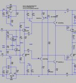
I mean to say about this circuit if you look at emitters of C4793 and C5200 they have resitors of values 120 and 220 1W resistors respectively connected to the output. Now how does that benefit of using such config than the Locanthi triple like where the resistors doesnt connect to the output rather connect between the two complimentary driver transistors by just using one resistor.
I was checking the other day about Meyer sound amplifiers Class AB/H and found that they are using some IRF140 or some Hexfet mosfet. I was quite interested to know that what if we use 15 pairs IRFp240/9240 instead of Bipolars like 6 pairs of MJL21194/93. One thing which attracts me is the no secondary breakdown in the mosfets i agree the fact about non linearity and other higher bias issues but in pro application like driving dual 18 inch subwoofers wouldnt mosfets are good enough. Now here is the question that what are points to consider if we use 15 pairs of IRFP240/ 9240 like a good TO264 package transistor would drive it? Consdier Im biasing each mosfet at about 20ma as its used more for the subwoofer application.
hi bob what if we a class A driver stage like in the pic then there is no chance that the current which is set would go out of class A. Please let me know about one more thing that I have seen some triples with drivers emitter resistors are split and connected to the output . Is there any advantage of it? As far as the stability is concern im playing with compensation caps across the base and collectors of the drivers.
The drivers in a Locanthi triple stay in class A unless their bias current is insufficient to turn off the output transistor when there is a very high rate of change of output current (i.e., when there is a lot of need to sweep minority carriers out of the base). This will be the case for most class A driver circuits. Connecting the driver emitter resistors to the output rail is usually not as good, since it allows the drivers to operate in class B.
Cheers,
Bob
Happy New Year! May all of your transistors have beta of 100 and all of your loudspeakers present an 8-ohm resistive load. May you also win the $500,000,000 lottery. Wait, I take that back. I'll take the $500M. Forget about the transistors and the loudspeakers.
Seriously, as responsible designers we are taught to take the worst case seriously, although I will admit that at times I have been over-conservative in making a point. If we want the highest performance in our amplifiers, everything matters.
But the numbers I quoted are not that far-fetched for the worst case. Minimum beta for the MJE15033 driver is only 50, and that minimum is only good up to 1 Amp. The very popular MJE21193/4 has a minimum beta spec of only 25 at 8 Amps and 5V Vce. Beta droop is very real, and Doug Self will also tell you that. The MJE21193/4 get onto the slippery slope of beta droop starting at only about 2A.
A less-experienced designer might assert that one will never require an output pair to deliver 8A in a reasonable design. Do the math. In my book I recommend that one output pair can be used for an amplifier up to about 75W into 8 ohms. At 75W, the peak output voltage will be 34.6V and peak output current will be 4.3A into 8 ohms. That amplifier will usually be expected to perform well into a 4 ohm load as well, at least in a consumer application (we assume good heat sinking and allow that it may not be asked to put sustained high power into a 4 ohm load). With a 4 ohm load, the amplifier will be called upon to deliver 8.6-Amp peaks into 4 ohms. So those MJE21193/4 output transistors may indeed have their beta fall to 25 according to the spec sheet. But not very often.
But let's also look at the case where we are using sustained-beta output transistors that can deliver minimum beta of 45 at reasonably high current, like the MJL3281/1302. If we assume beta of 50 for both the driver and output devices in a 2 EF output stage, we have current gain of 2500. Sounds like a lot? No. With a 4-ohm load, the output stage loads the VAS with a very nonlinear 10k ohms. Do you want your VAS to be really loaded like that?? After all that work you put into the rest of the amplifier? Just to save a dollar or two by not using pre-drivers and implementing a Triple?
Take a look at Chapter 3, Section 3.5 in my book. There I take a decent, plain-vanilla Miller-compensated amplifier design and change the output stage from a Double to a Triple and compare the difference in THD-1 and THD-20 at various load resistances. You need go no further than compare Chart 3.4 to Chart 3.5 to see the obvious benefit of using an output triple. These comparisons are based on simulations that use accurate typical models of the MJL21193/4. Even with just an 8-ohm load, THD-1 is cut by a factor of 8, and THD-20 is cut by a factor of 2.4.
The great Bart Locanthi taught us the value of using triple output stages in the late '60s when I was still in High School, and a great many top designers since followed his advice, including Barney Oliver of HP. Yes, transistors have improved since those days of the 2N3055 and the MJ802, but Bart's advice still rings true.
Cheers,
Bob
1. Bob I have question with error correction using Mosfets in OPS. What I have heard from few friends is that error correction doesnt sound as good as a simple biased OPS. Can you please tell me that is it really so.
2. How many IRFP240/9240 pairs can be driven using a single 2sc5200 or NJL transistor at 80V?
2. How many IRFP240/9240 pairs can be driven using a single 2sc5200 or NJL transistor at 80V?
I have been going through this link about arcing in the amplifiers in pro application where the dew point giving problems in arcking. Please go through this interesting link about Crest 9001 amplifiers https://splnetwork.com/not-everything-scalable-08202014/
How to avoid such dew point scenarios and as well as where do we find these laminated bus bars. I have seen it on few pics but never searched for it.
How to avoid such dew point scenarios and as well as where do we find these laminated bus bars. I have seen it on few pics but never searched for it.
1. Bob I have question with error correction using Mosfets in OPS. What I have heard from few friends is that error correction doesnt sound as good as a simple biased OPS. Can you please tell me that is it really so.
2. How many IRFP240/9240 pairs can be driven using a single 2sc5200 or NJL transistor at 80V?
I have not heard anything bad about error correction, but there are not that many commercial amplifiers out there that use it (at least HEC). The Halcros used a version of my HEC implementation and they were well-regarded. What amplifiers were your friends referring to?
It is difficult to answer your second question without some significant analysis and choice of a complementary pair of drivers.
Cheers,
Bob
I have been going through this link about arcing in the amplifiers in pro application where the dew point giving problems in arcking. Please go through this interesting link about Crest 9001 amplifiers https://splnetwork.com/not-everything-scalable-08202014/
How to avoid such dew point scenarios and as well as where do we find these laminated bus bars. I have seen it on few pics but never searched for it.
Entertaining article and a nice walk down memory lane. I consulted on the design of the Crest 8001. I recall having to hot-wire a 30-Amp line from my dryer outlet to test it in my basement.
There is probably a lot more detail to why they had "lightning" as a result of some condensation. Even with 150-V rails it seems a little unlikely assuming they had adequate trace spacings and good soldermask. This assumes the problem was on the PC board. But mention of bus bars suggests otherwise. I have not seen laminated bus bars. Maybe they had +/- HV rail bus bars in very close proximity to each other and some condensate got in between. It is easy to imagine that they would have used large bus bars, given the currents involved in delivering that amount of power. Also, once enough condensate caused an arc with ionization, extremely high currents can flow and a lot of light can be created
") . Anyway, it sounds like the guy who did the physical design pushed things a little to close. I'm sure it was a sight to behold!
. Anyway, it sounds like the guy who did the physical design pushed things a little to close. I'm sure it was a sight to behold!Cheers,
Bob
- Status
- This old topic is closed. If you want to reopen this topic, contact a moderator using the "Report Post" button.
- Home
- Amplifiers
- Solid State
- Driving 8 pairs of MJL21194/93