We used to buy those insulated buss bars to distribute +5V across big BIG cards full of wire wrap DIPs. You can see them on the Jeff Rowland Model 10 amplifier photos, look for the orange sticks. They're actually a distributed transmission line (supply and ground) with ceramic capacitors built-in throughout. Notice that the orange sticks connect to two different PCB networks: supply and ground.
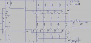
Jeff Rowland LM3886 Amplifiers
Jeff Rowland LM3886 Amplifiers
<snip> The great Bart Locanthi taught us the value of using triple output stages in the late '60s when I was still in High School, and a great many top designers since followed his advice, including Barney Oliver of HP. Yes, transistors have improved since those days of the 2N3055 and the MJ802, but Bart's advice still rings true.
Cheers,
Bob
Who is arguing that a triple EF isn't technically better than a double EF? It's the evangelism and pretentiousness here that is absurd. So Self perhaps has not put a design into production with a triple EF OPS and you allegedly haven't built an amplifier with anything less since high school. Does that make you intellectually superior? Is Self now not "a serious designer" and are all of these designs put out by Self over what must be a few decades now, presumably enjoyed by tens of thousands, despite their wholly adequate objective performance, now revealed to be unfit for the originally intended purpose?
Even Self has a whole chapter in one of the later editions of his own book (which I think might even predate the publications of yours) on triple output stages (with actual amplifier measurements as opposed to SPICE simulations) in which he appears quite enthusiastic about the overall reduction in distortion.
And to put your original comments back into context you suggested a minimum output transistor beta of 20 for a proposed design delivering 16A peak into a 4R load with 6 to 8 parallel pairs.
Last edited:
I think its always better to be very conservative on the beta of transistor especially in the OPS I see alot of transistors droop badly and one forgets the temperature rise of the die when such beta droop comes in play. No matter what I strongly feel even thermal compression in transistors play a significant role. Coming to the triple I have tested triple with large driver TO 264 to drive 5 pairs of output transistors and just with 0.5V of input and with gain of 50 to the amp i was blown away by the way it delivers the power it was hardly 25V peak on the CRO and the way it was able to hold the driver was amazing at that voltage output. I will never build an amp without a triple from now.
Dry air has dielectric constant of 20KV per centimeter. 150V even with moist air.
No way. Unless the moister is carrying ions. And it's forced air. How is it going to condensate.
Especially in an amplifier running that hot. The heat raises the dew point. That air would dry out so quickly.
The story is totally illogical.
No way. Unless the moister is carrying ions. And it's forced air. How is it going to condensate.
Especially in an amplifier running that hot. The heat raises the dew point. That air would dry out so quickly.
The story is totally illogical.
Last edited:
ok in general what is the clearance required for
1> upto 100V of operation without issues
A> Pad to pad distance , B> Route to Route distance
2> Upto 200V of operation same cases as above
A> Pad to pad distance , B> Route to Route distance
Bob I have a doubt regarding the heatsink / thermal dissipation from the OPS transistors.
Consider I have a sub amplifier at +/-70V DC with MJL21194/93 5 pairs and I have been driving it at 1/3rd of the maximum clipping voltage output. Approx 20V or so then if the heat dissipated through the output transistors is making the heatsink just warm then would that be dissipating lesser heat at 70% or 90% of the output? Its just to understand that my heatsink would be sufficient to deal with the heat at higher output power?
on the LTspice sim im able to see the dissipation curve is like half sinewave at max 90W at about 1/3rd the output and there is a notch on the curve at higher power like M shape but not crossing more than 100W.
Regarding the Mosfet driver if we use it in conventional EF I believe the loading of the VAS transistor will be substantial because of the mosfet ciss. Now considering triple for the same application where a pre driver will be eventually be able to drive the mosfet with ease even the IRFp240 by 2sc5171 should be able to drive it with full potential. Now what is the use of having Mosfet in the driver stage? As per the simulation the THD dropped even further but sonically does it offers any benefits especially in bass or mid or treble?
as Mosfets are not as linear as transistors but using a mosfet to drive the BJT OPS would that inject the mosfet signature in the amp?
Attachments
I think its better to drive the mosfet with a better pre driver than directly driving from VAS.Can the mosfet ciss be tamed using cascode bootstrap?
Hi Bob I have a doubt regarding the SOA with restpect to Ic vs Vce where in the following example where you can see that green being the output voltage swing of the amplifier. Red curve is Voltage across Collector and Emitter of the output transistor and Blue being the current through the transistor.
Now I have a doubt that at full swing the voltage across Collector and Emitter is dropped as much as 20V and thats where the Ic is at its peak so what is the use of selecting High SOA transistor when the Vce is low enough and Ic being at its peak which will be about 7Amp DC at 20V for 2sc5200.
I think its better to drive the mosfet with a better pre driver than directly driving from VAS.
Hi Bob I have a doubt regarding the SOA with restpect to Ic vs Vce where in the following example where you can see that green being the output voltage swing of the amplifier. Red curve is Voltage across Collector and Emitter of the output transistor and Blue being the current through the transistor.
Now I have a doubt that at full swing the voltage across Collector and Emitter is dropped as much as 20V and thats where the Ic is at its peak so what is the use of selecting High SOA transistor when the Vce is low enough and Ic being at its peak which will be about 7Amp DC at 20V for 2sc5200.
I meant tiny mosfets as predrivers. Like the BSS123 or the like. Bootstrap them to kill the ciss and follow it with an 2EF.
A problem with mosfet drivers is you can't take the bipolars to rail.
can you explain what do you mean by mosfet drivers cant take the bipolars to rail.I meant tiny mosfets as predrivers. Like the BSS123 or the like. Bootstrap them to kill the ciss and follow it with an 2EF.
A problem with mosfet drivers is you can't take the bipolars to rail.
@rhythmsandy
A mosfet output stage using verticals requires the driver stage to operate at higher voltage rail than the output devices. Usually in the order of 15 volts higher if you want to get the outputs to rail. It makes no difference if the the mosfets are drivers to bipolar. The bipolar won't go to rail unless the mosfet gate is driven from significantly higher voltage. See Bob's mosfet amplifier with error correction.
The small signal mosfets don't seem to suffer from this as much.
I believe JC used laterals in the Parasound.
Last edited:
Now I have a question especially for Mosfets for a sub amp that I have a thought to use about 5 pairs of MJL21194/93 for the subwoofer amp with large driver driven by a 2sc5171 but would like to take a call about why not use Mosfets instead but as per the calc we need about 10 pairs of IRFp240/9240 in the OPS. Now what is the choice? BJT with MJL21194/93 or IRFp240/9240? What I require is excellent grip and definition in bass even at super low frequency and yet be very reliable.
Ill be using it about +/-73VDC for a load of about 3.5ohm. I have checked the damping factor of both as mosfet as drivers and also BJT as drivers in triple with a resultant DF value of 2000 in both the cases with 0.0017mohm at 100Hz. Now how does BJT or mosfet perform in both the cases.
I have heard amplifiers from Labgruppen with MJL21194/93 and they sounded just mind blowing in terms of low frequency grip and body in bass and i have found the DF was just 160 with 25mohm output impedance. Im sure many say that high DF is not really important. So what is the conclusion towards which one to go with. Looking at Meyer one of the very famous PA systems in the world still use class AB/H but with mosfets. So what does that mean? Is there anything that Im missing here. I know some prefer BJT and some prefer mosfets but in my sub bass application both seem good to me but is there anything that needs to be considered in above cases?
Last edited:
Don't get me wrong. I'm not saying not to use mosfet drivers but you will need to use elevated voltage on the drive to the mosfet gates if you want to get the most out the bipolar.
I'm trying to equate the term punch, as an example term, to something technical. Power supply drop could be one reason for this or simply not enough current to the base of the output transistors under large dynamic and heavy loading.
Negative feedback drives the output impedance down which means part of the output impedance is dynamic and can change with frequency. Speaker load varies with frequency as well.
It's not an easy question to answer without doing a lot testing on the amplifier and knowing the speaker behavior. Some high end speakers can take the load down to as low as 2 ohms. The worst I've seen is 1 ohm. No names mentioned but nasty.
There are lots of reasons for this lack of punch or in "terms of low frequency grip and body in bass.".
Last edited:
- Status
- This old topic is closed. If you want to reopen this topic, contact a moderator using the "Report Post" button.
- Home
- Amplifiers
- Solid State
- Driving 8 pairs of MJL21194/93