rythmsandy,
You seem to be confused between the subwoofer physical implementation and the amplifier design. They are related, but actually two very different things.
What I mean by this is:
- The subwoofer design is what it is. If may use a large driver, a heavy cone, whatever. Ultimately however it presents to an amplifier an electrical load. Follow me here...
- An amplifier, well a conventional one as being discussed here, is a voltage source. That is able to deliver voltage into a specified (read range of) loads. It doesn't care if the subwoofers cone is 25 grams or 1500 grams.
Your continued concern at the mass of the subwoofer driver misses the critical point that as an amplifier designer you need to know what electrical load it presents to the amplifier. Without nailing this down, you really don't know what you need to design.
The other thing you need to know is how much power you need to deliver to said subwoofer. This depends on the electro acoustic efficiency of the device. You keep talking about numbers in excess of a kilowatt. I assume this is because the driver has huge mass and is consequently rather inefficient - but I do assume.
You should be able to get clean bass from your 1.5kg subwoofer with a very modest amplifier - but limited to less than earth shattering levels. Indeed a 100 Watt amplifier will be only "somewhat" less loud than a 1,000 Watt amplifier.
Is this the case?
Your repeated comments about needing to control the weight etc, worry me. I kind of wonder if you have a speaker design issue you are trying to fix with am amplifier.
In Kitsilano in Vancouver on 4th avenue there used to be a surplus electronic store. One of my business partners was doing a bit of shopping there one day many years ago. He notice this peculiar sound as this other shopper moved around. He said to Headley, the shop owner, "What's with this guy?". Headley said "that guy is in here all the time and he's pretty strange.", he said, "he's wrapped in aluminum foil and hooks himself up directly to his amplifier because he want's to feel the base."
Last edited:
I wanted to understand how to drive number of mosfets.
Can you please tell me which driver to use to drive 14 or 20 pairs of IRFs Yes I'm looking to drive a 21 inch pro sub with full grip.
I have a doubt reg sub amp with 5 pairs of MJL21194 / 93 or 10 pairs of IRF240/9240 to drive a sub at 600W into 4ohm? at +/-80V supply. I'm looking at super low frequency with full grip and control. Which one do you suggest and why?
Yeah , just class D your 20-100hz sub. The Rdson of a modern class D output is so low . Damping factor and "control" is magnitudes better. Use AB (+G)
 for 100hz up. 500W sub amp fits in my palm. 600W SMPS also fits the palm. No heat to speak of , throw them in the speaker , let port turbulence be the cooling.
 PS - some class D sub amps will do 2R 1KW easy.
OS
It was all about the current delivery capability into a tough reactance load. I own a buttkicker but driven with a low bias class AB plate amp of 300W bought off the shelf and the amp was getting real hot.
I think I found the solution for delivering ample current into the loads with MJLs crossconduction also seems not an issue at lower frequencies hence 21194/93 can be dedicated only for the sub application and MJL3281s and other for mids and highs.
I do have plan for a 21 inch pro subwoofer to drive. I know cinema theater installation guys who have done more than 500 cinema Theater installations and my partner is into pro audio and their input is 21 inch feels lazy as if like impulse is not as fast or nice as an 18 inch and the were telling they never found an amp which can do justice to a 21 inch sub. Looking at Class D few said the efficiency of the output coil drops like crazy at super low frequencies hence not much effective in conversion. I have heard labgruppen loved the way it was controlling the speaker. Class TD and after seeing the sch realized its power is in D and actual amp is in AB. The damping factor is also in the order of 150 or so even then the grip was way too good and what caught my attention is I found 21194/93 in triple config. Proline 3000 some have expressed as the following>
>>
I have a proline 3000 running my 2x18 subs @4ohms.... it's not the volume that they produce which is awesome, it's the intensity of the subsonic waves that hit you. the only other kit that does this type of thing that ive heard (only Better) are the L.A Acoustic 2x18 subs (The manufacturer designed the subs I had around the L.A Acoustic kit. but i never said that). the way the 3000 bass restores after a big push, i.e bass drum kick. is just mind blowing. It just doesn't get out of breath no matter how hard you push them."
>>
you can see what other members who are into proaudio said this>>
l understand what you are asking, no doubt this will cause the usual debate but here's my take on it, if I use my general purpose bass bins from 40hz and up then class D is ok, if I lift them and put my subs under it's a different story, my subs genuinely go down to the low 20s and only big toroidal amps sustain big long notes at these frequencies, yes I have done extensive testing using various class D amps and in my opinion they don't come close to my Crests, I hope this gives you something to go on.
>>
Seems that the current delivery of the Mjl is somewhat very sustained and can control the driver with excellent grip.
I learnt new things about crossconduction and its consideration in this thread.
Hi Googlyone I know exactly what I want. Calculate how much energy is required to stop a 1kg mass vibrating at 100Hz to an absolute standstill you will be surprised how much energy you need you cannot defy physics atleast in this dimension. Im not talking about voltage here into the load I was talking more about current.
Last edited:
Hi Sandy,
Yes, but to generate that current, you have to present the driver with a lot of volts, otherwise that current simply will not flow. You can't separate voltage from current.
If you have a fanboy recommending the Crest amplifiers, why don't you just buy them and be done with it?
Understand too, the speaker and enclosure (it's more than just a box) will determine what the speaker does with the power you are dumping on it. So it has to be up to the task in your installation. The same driver can perform wonderfully, or it can really disappoint depending on your enclosure. The tiny subwoofer boxes are supposed to treat the woofer like a piston with little regard for Thiel and Small. A larger enclosure that is also tuned will be far more efficient, and depending on the size of that enclosure, might bury the same driver in a box (untuned = box).
Just for chuckles and grins, get the T&S parameters and feed them into a speaker enclosure program to see what you end up with. It might be a fantastic system, or a complete dud. Time to use it just as a piston in a small box in that case. May as well really find out what you have and how the performance might be.
As for your plan to hit these with over a kilowatt, consider mounting a temperature sensor to the motor assembly to monitor the operating temperature. It would be a real shame if you built a dream amplifier only to cook your dream woofer. Physics rules here!
-Chris
Yes, but to generate that current, you have to present the driver with a lot of volts, otherwise that current simply will not flow. You can't separate voltage from current.
If you have a fanboy recommending the Crest amplifiers, why don't you just buy them and be done with it?
That characteristic is called damping factor, and it is the result of the entire amplifier. The outputs are pretty much invisible as long as they can deliver the power as demanded by the rest of the amplifier. If they can't, they blow up. If they can safely, then the bass should be tight ("grip" I'm guessing) without a depressing event happening. But, if the voltage amp or driver stages are rubbish, low damping factor and sloppy sounding bass.Seems that the current delivery of the Mjl is somewhat very sustained and can control the driver with excellent grip.
Understand too, the speaker and enclosure (it's more than just a box) will determine what the speaker does with the power you are dumping on it. So it has to be up to the task in your installation. The same driver can perform wonderfully, or it can really disappoint depending on your enclosure. The tiny subwoofer boxes are supposed to treat the woofer like a piston with little regard for Thiel and Small. A larger enclosure that is also tuned will be far more efficient, and depending on the size of that enclosure, might bury the same driver in a box (untuned = box).
Just for chuckles and grins, get the T&S parameters and feed them into a speaker enclosure program to see what you end up with. It might be a fantastic system, or a complete dud. Time to use it just as a piston in a small box in that case. May as well really find out what you have and how the performance might be.
As for your plan to hit these with over a kilowatt, consider mounting a temperature sensor to the motor assembly to monitor the operating temperature. It would be a real shame if you built a dream amplifier only to cook your dream woofer. Physics rules here!
-Chris

It was all about the current delivery capability into a tough reactance load. <snip>
It is true that not all class D amplifiers are created equal, especially those that use switching power supplies (most). To first order, SMPS and class D amplifiers are a match made in heaven. However, both SMPS and class D amplifiers have their own quirks and characteristics, and some of these can reveal themselves at very low frequencies and very high power levels.
Bus pumping is one phenomena of class D amplifiers worth keeping in mind. While it can be a bit difficult to describe in short, simple terms, it refers to the fact that a class D amplifier when driving a load can deliver energy from the positive supply to the negative supply, and vice versa. This is partly because the output stage of a class D amplifier is not unlike a switching power supply. This can cause strange things to happen if the rail receiving the extra energy cannot absorb that energy in some way. Fortunately, most high-power class D amplifiers are so-called Bridge-Tied-Load in nature, a class-D way of describing what is essentially a bridged amplifier configuration. When properly applied, bus pumping effects are significantly mitigated because the energy pumped into a given rail by one side of the output is used (sunk) by the other side of the BTL output.
Another phenomena is that some class D amplifiers have rather poor power supply rejection, depending on details of their design. If the rails are moving around a lot due to delivery of very high current into a load, some degradation can occur.
Finally, energy storage in an SMPS used to power a class D amplifier can be an important issue. Because the ripple frequency in an SMPS is at a high frequency, large reservoir capacitors are not required to get ripple small. However, this can bring on complacency in reservoir capacitor sizing in regard to energy storage needed to sustain very high power bursts over a long cycle. Those 100,000 uF capacitors charged to 100V or more in our good old high-power class AB/G amplifiers store a lot of energy! Where is that amount of energy storage in an SMPS used for that same amplifier? This is the question. It may be there, or it may be made up for in some SMPS designs, but it may not be there in all SMPS designs for class D power amplifiers.
In many SMPS, really large reservoir capacitors are not used on the secondary side where the rails are. However, the SMPS first rectifies the incoming AC to a high-voltage intermediate bus prior to the isolating SMPS-proper. Often it is there, on the primary side, where there may be a lot of energy storage, where the DC voltage may be on the order of 350V. That supply side may even be made stronger by the proper use of active power factor correction prior to the intermediate bus. PFC does a better job of extracting the most power out of the line, since it does not just take power in the form of very large rectifier transients, but rather extracts power over most of the cycle.
However, even if there is really good power and energy storage on the primary side, large bursts of current drain must be supplied in real time by the main SMPS itself if there is not a lot of energy storage on the secondary side. This means that the SMPS may need to be very over-designed to sustain those very high current bursts. SMPS also sometimes do funny things when asked to deliver more current than their design maximum. They do not often sag or "fail to deliver" gracefully (like a good old linear supply with a big transformer and big reservoir capacitors). Most SMPS want to create a stiff, regulated output until they reach their maximum current output. Beyond that, all bets are off as to what they will do.
Cheers,
Bob
Thanks for the experience written down in post 126 rhythmsandy. I've recently been offered an 18" Allen organ speaker, about the same time I noticed that piano & organ notes go to 27 hz, not the 54 my speakers roll off at. The huge organ boxes are port tuned down to 20 hz so I'll be diving off into the subwoofer world soon. No wonder my wood piano sounds better even with unprofessional me pushing the keys. A use for the PV-1.3k I picked up for $55, which has 5 pairs MJ21193/94 now it is repaired.
Bob Im thinking of a situation in using Balanced amplifier configuration. There are two cases I thought of using 5 pairs of MJL21194/93 in the +/-70V amplifier for a 500W RMS into 4ohm load with current in load being at roughly 20Amps. Now calculating the current demand from each MJL transistor is about 4Amps for which it can deliver with ease ( Now look at the beta droop at 4Amp which is about 60 and for 1Amp delivery the beta is about 75. Now consider when using the amplifier in fully balanced amplifier at +/-40V where I thought of using 3 pairs of MJLs on each half. Now if you look at the current delivery from each MJL transistor is about 6.7Amps consider about 7 amps with little headroom. The amount of beta drop at 7Amp is about 40. Now considering the fact of driving such low beta requires more demand on the drivers hence consider we need more current from drivers and little bit more current even from pre drivers. Now my question is if we do use MJLtransistors in the above case where beta might drop to 40 or 30 in worst case and if the driver is able to deliver enough current to the OPS then the beta sag wont effect the performance? Im just thinking that wouldnt that be like transistor struggling to deliver the current? Like its capability of delivering the current is degrading and hence might not deliver the current as effectively as when 4amp is demanded at higher 70V?
Looking towards Mosfet here as I found a IRFP240 Fairchild Datasheet and its states the DC current delivery of the IRFP240 is half that of MJL21194. So there is no beta droop in mosfets so is it ideal to choose 5 pairs of mosfets in each half in the case? Or using an 3 pair of MJL21194/93 per each half of the balanced amp?
Looking towards Mosfet here as I found a IRFP240 Fairchild Datasheet and its states the DC current delivery of the IRFP240 is half that of MJL21194. So there is no beta droop in mosfets so is it ideal to choose 5 pairs of mosfets in each half in the case? Or using an 3 pair of MJL21194/93 per each half of the balanced amp?
Class d in btl and bus pumping issue is past, run it from boat anchor toroid and huge cap bank.. did that with 4 irfp4227 rated at 65 amps each.. current ad libitumIt is true that not all class D amplifiers are created equal, especially those that use switching power supplies (most). To first order, SMPS and class D amplifiers are a match made in heaven. However, both SMPS and class D amplifiers have their own quirks and characteristics, and some of these can reveal themselves at very low frequencies and very high power levels.
Bus pumping is one phenomena of class D amplifiers worth keeping in mind. While it can be a bit difficult to describe in short, simple terms, it refers to the fact that a class D amplifier when driving a load can deliver energy from the positive supply to the negative supply, and vice versa. This is partly because the output stage of a class D amplifier is not unlike a switching power supply. This can cause strange things to happen if the rail receiving the extra energy cannot absorb that energy in some way. Fortunately, most high-power class D amplifiers are so-called Bridge-Tied-Load in nature, a class-D way of describing what is essentially a bridged amplifier configuration. When properly applied, bus pumping effects are significantly mitigated because the energy pumped into a given rail by one side of the output is used (sunk) by the other side of the BTL output.
Another phenomena is that some class D amplifiers have rather poor power supply rejection, depending on details of their design. If the rails are moving around a lot due to delivery of very high current into a load, some degradation can occur.
Finally, energy storage in an SMPS used to power a class D amplifier can be an important issue. Because the ripple frequency in an SMPS is at a high frequency, large reservoir capacitors are not required to get ripple small. However, this can bring on complacency in reservoir capacitor sizing in regard to energy storage needed to sustain very high power bursts over a long cycle. Those 100,000 uF capacitors charged to 100V or more in our good old high-power class AB/G amplifiers store a lot of energy! Where is that amount of energy storage in an SMPS used for that same amplifier? This is the question. It may be there, or it may be made up for in some SMPS designs, but it may not be there in all SMPS designs for class D power amplifiers.
In many SMPS, really large reservoir capacitors are not used on the secondary side where the rails are. However, the SMPS first rectifies the incoming AC to a high-voltage intermediate bus prior to the isolating SMPS-proper. Often it is there, on the primary side, where there may be a lot of energy storage, where the DC voltage may be on the order of 350V. That supply side may even be made stronger by the proper use of active power factor correction prior to the intermediate bus. PFC does a better job of extracting the most power out of the line, since it does not just take power in the form of very large rectifier transients, but rather extracts power over most of the cycle.
However, even if there is really good power and energy storage on the primary side, large bursts of current drain must be supplied in real time by the main SMPS itself if there is not a lot of energy storage on the secondary side. This means that the SMPS may need to be very over-designed to sustain those very high current bursts. SMPS also sometimes do funny things when asked to deliver more current than their design maximum. They do not often sag or "fail to deliver" gracefully (like a good old linear supply with a big transformer and big reservoir capacitors). Most SMPS want to create a stiff, regulated output until they reach their maximum current output. Beyond that, all bets are off as to what they will do.
Cheers,
Bob
Something like this..Class d in btl and bus pumping issue is past, run it from boat anchor toroid and huge cap bank.. did that with 4 irfp4227 rated at 65 amps each.. current ad libitum
Attachments
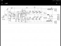
I initially thought of Class D in the same way but was not confident of IRS2092 for its stability and bass slam. Im going through the linear route right now till I get a decent performing Class D. How did sub bass sound with the above circuit? What was the voltage with which it was running. The DF is a bit lower i think in 150 or so but I think that is still ok.
The shown schematic was just an example, but mine is similar, it's running on +/- 75 volt, for bass duty only working frequency could maybe be lowered also output inductor could be modified as it is designed for full audio spectrum, but that would be way above my paygrade calculating thoseI initially thought of Class D in the same way but was not confident of IRS2092 for its stability and bass slam. Im going through the linear route right now till I get a decent performing Class D. How did sub bass sound with the above circuit? What was the voltage with which it was running. The DF is a bit lower i think in 150 or so but I think that is still ok.
Regarding the mjl21193/mjl21194, i have 8 of each from an scrapped d.a.s audio amp, a guy in swapmeet sold lme49830 driver chips so I bought 4, so that's my approach, I'm not much for theorizing I like building stuff, the succes rate is so so, but I'm having fun.of what if to drive 10 pairs of IRFP240s to be driven? which driver configuration to be used? Any existing ideas to drive a large bank of mosfets? How stable will they be?
I don't own a big high end stereo setup, I'm not building to reach some glorified goal, it's the road that drives me.
- Status
- This old topic is closed. If you want to reopen this topic, contact a moderator using the "Report Post" button.
- Home
- Amplifiers
- Solid State
- Driving 8 pairs of MJL21194/93