Having completed my HPA-1 and J2 clones (Pictures of your diy Pass amplifier), I'm back on this project.
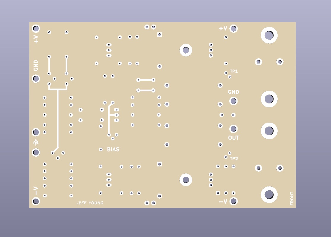
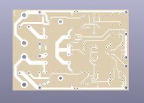
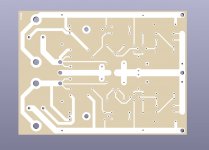
I've decided to do my boards without solder mask and silkscreen so they look more old-school. They'll still be two-layer with plated-through holes, so not completely old-school. But care will need to be taken when soldering to check for bridges.
Legends will be sparse (connections, test points and pots) and done in copper.
Amp front:
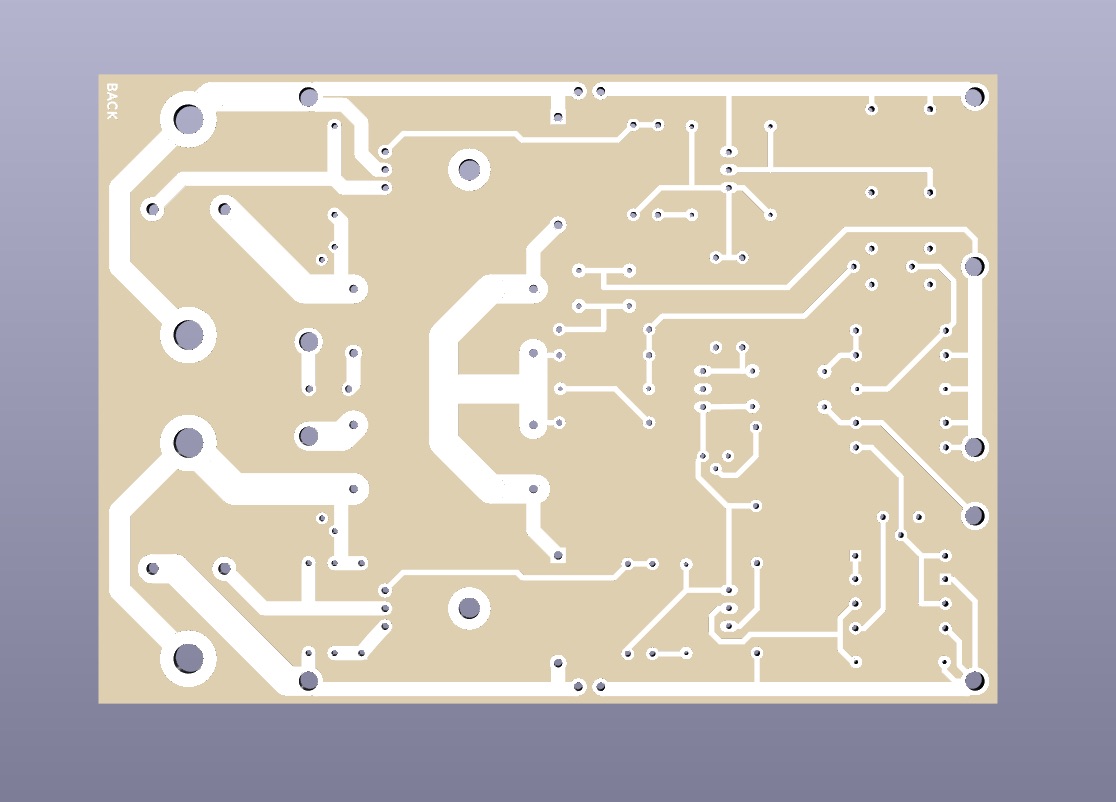
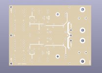
Amp back:
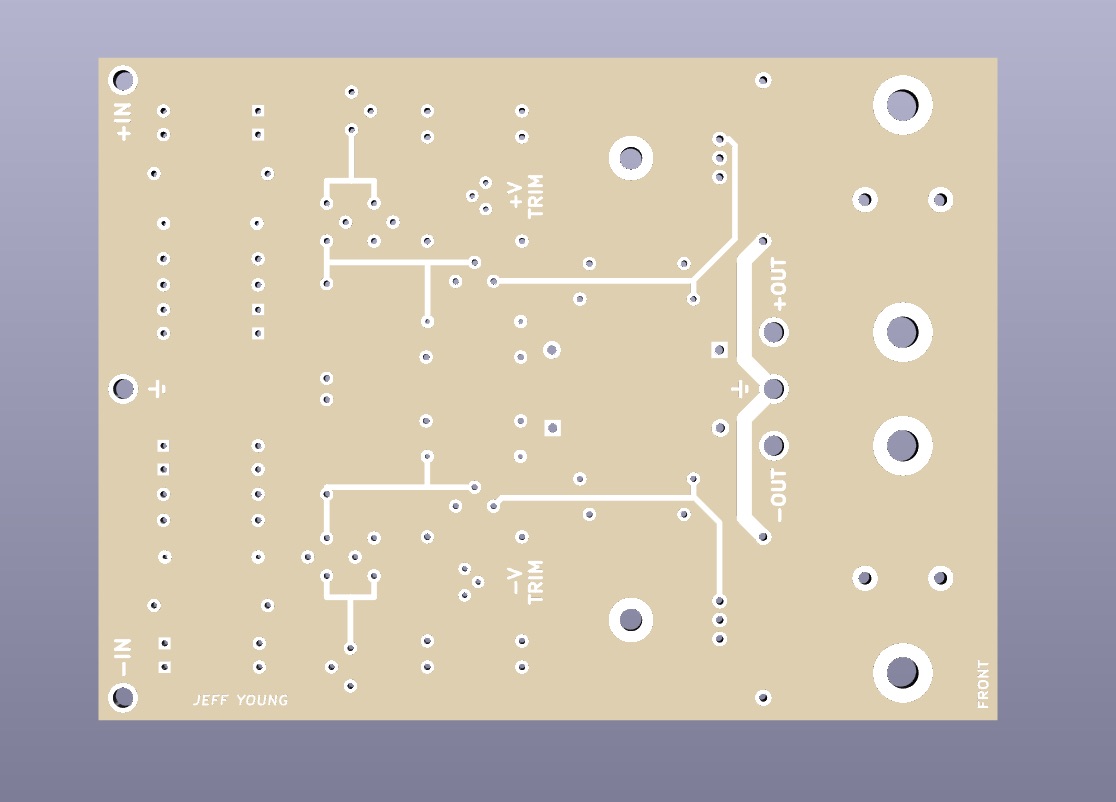
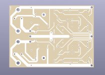
Inverted regulator front:
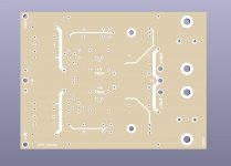
Inverted regulator back:

Anyone interested in a small group-buy? I'll be making the boards at EuroCircuits (made in EU) so they'll be more expensive than Chinese-made boards. Price will also depend heavily on volume. Figure between €10/board and €20/board.
Also let me know if you'd be interested in the original or inverted regulator boards (or both). Note that the amp boards have jumpers so you can power either the whole amp or just the front-end from the regulators.
Cheers,
Jeff.
I've decided to do my boards without solder mask and silkscreen so they look more old-school. They'll still be two-layer with plated-through holes, so not completely old-school. But care will need to be taken when soldering to check for bridges.
Legends will be sparse (connections, test points and pots) and done in copper.
Amp front:
Amp back:
Inverted regulator front:
Inverted regulator back:
Anyone interested in a small group-buy? I'll be making the boards at EuroCircuits (made in EU) so they'll be more expensive than Chinese-made boards. Price will also depend heavily on volume. Figure between €10/board and €20/board.
Also let me know if you'd be interested in the original or inverted regulator boards (or both). Note that the amp boards have jumpers so you can power either the whole amp or just the front-end from the regulators.
Cheers,
Jeff.
Attachments
Is there a reason for no solder mask other than appearance?
Copper is a fairly active metal and will corrode quite quickly. to make things worse, IINM, you can make a diode with a copper=copper oxide junction.
If you want the boards to last as long as the components, I strongly advise some protective coating.
Copper is a fairly active metal and will corrode quite quickly. to make things worse, IINM, you can make a diode with a copper=copper oxide junction.
If you want the boards to last as long as the components, I strongly advise some protective coating.
... Copper is a fairly active metal and will corrode quite quickly...
Even without a solder mask the copper still has a protective coating of tin.
I've repaired a bunch of little amplifier circuit boards for the coolant level and outside temperature sensors in 1960s and 70s RR/Bentleys that have been sitting around in British Isles humidity for nigh on 50 years. 90% of the time it's the diodes that fail, with the odd transistor or rivet that attaches the pins to the board. But I've never had an issue with oxidation on the board itself. (I do spray the entire assembly with cellulose lacquer after replacing the diodes and transistors, but that's just because they're going back out in the weather again.)
Use transparent solder mask perhaps?
Yeah, I actually tried that, but sadly it kicks you out of the pooling and the board cost goes way up.
Would it be worth opening a dedicated group buy thread?
I'd be interested in 2 amp and 2 inverted regulators but dependant on price.
I didn't originally because I didn't want to get flooded with 70 subscriptions like with my J2 boards. But this appears to have much less interest, so I think I will put up a GB thread....
[Edit: thread is up: https://www.diyaudio.com/forums/gro...-amp-boards-regulator-boards.html#post5965534 ]
Last edited:
Hi Jeff,
Any clues as to where to source the BC239C input transistors and either of the output TO3 metal can types you have on the schematic. Not stocked at Mouser. All the other transistors are in stock in qty at Mouser , so no problems with those.
Or, have you further alternatives, should not be too hard for the inputs TR1 and TR2. Maybe the output stage TR11 and TR12 need to be as close to original design semi's as possible.
Look forward to your thought on these devices. Also posted this in your GB thread.
Also, have you posted the schematics for both regulator design's?
Gary..
Report Post
Hi Gary,
I replied on the device questions in the GB thread.
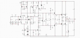
I probably posted both regulator schematics, but it's easier to do it again than to find them.")
Julian's regulator:

My inverted version:

Cheers,
Jeff.
I replied on the device questions in the GB thread.
I probably posted both regulator schematics, but it's easier to do it again than to find them.
Julian's regulator:
My inverted version:
Cheers,
Jeff.
Attachments
Even without a solder mask the copper still has a protective coating of tin.
OK, good - you have a protective layer.
I did a lot of home etch boards back in the day and they did not hold up well, even with good post etch cleaning. Maybe city air quality has an accelerating effect but bare copper isn't a longevity play.
- Home
- Amplifiers
- Solid State
- NAP250 clone