Sry, but in my opinion, there was nothing better then a pair of 2SC2922 and MJE as it is.there are only the output transistors that are "not too much"
critical.
2SC2922 is absolute also

Different outputs means that everything must be replaced
with bd 743c and bd 901 you could make very good sounding small amplifier:have a lot of real sc2922
Upper RC filter 27R+33R+470pF, lower RC filter 560R+390R+470pf, dont forget MJE253/243 + use 68uF Solid tants on feedback and bias, ESR of ~0.5 - 0.6R
then i would make small PSU +/- 25V, better if regulated with 300VA toroid.
This setup should give plausable BASS response, very very tight
with the inductor at the output.Reply to Jeff's first draft:
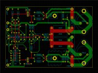
That's very impressive presentation and nice PCB work.
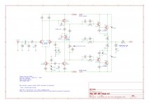
Incidentally, the bias voltage between TP1 and TP2 should be approximately 2 x 7.2mV for a Naim clone.
As you can read in Julian Vereker's interviews, his concern for the type of output transistor was focused on switching speed to reduce crossover artefacts. Power transistors were still quite slow in the 70s and switching types, such as BDY56,58 that were produced for SMPS and similar applications, were preferred - even to more linear power transistors.
Now that we do have very fast power transistors, its possible to switch fast and have good gain linearity - the best of both, as Naim quickly realised when they adopted the fastest Sanken LAPTs back in the 1980s. They haven't stopped there and their latest models continue to exploit more exotic output semis in the push for faster switching speeds, better linearity etc.
I wouldn't seriously consider the slow MJ series of power transistors. BUV20 is more in the medium speed switch category of the early Naim transistor types like BDY56 and 58. However, they are also history in terms of sound quality now and it would be a retrograde step to use them IMHO, when you can still buy OEM 2SC2922 type Sanken LAPT transistors in a TO3P package. 2SC3263 is the direct (same chip) replacement type. Profusion in the UK carry a good range of Sanken power semis including this one and I don't see any dissipation problems using the smaller package, given the realistic power limits for domestic use. A substantial heat spreader bar and thick case is the key to Naim reliability in any event.
That's very impressive presentation and nice PCB work
.Incidentally, the bias voltage between TP1 and TP2 should be approximately 2 x 7.2mV for a Naim clone.
As you can read in Julian Vereker's interviews, his concern for the type of output transistor was focused on switching speed to reduce crossover artefacts. Power transistors were still quite slow in the 70s and switching types, such as BDY56,58 that were produced for SMPS and similar applications, were preferred - even to more linear power transistors.
Now that we do have very fast power transistors, its possible to switch fast and have good gain linearity - the best of both, as Naim quickly realised when they adopted the fastest Sanken LAPTs back in the 1980s. They haven't stopped there and their latest models continue to exploit more exotic output semis in the push for faster switching speeds, better linearity etc.
I wouldn't seriously consider the slow MJ series of power transistors. BUV20 is more in the medium speed switch category of the early Naim transistor types like BDY56 and 58. However, they are also history in terms of sound quality now and it would be a retrograde step to use them IMHO, when you can still buy OEM 2SC2922 type Sanken LAPT transistors in a TO3P package. 2SC3263 is the direct (same chip) replacement type. Profusion in the UK carry a good range of Sanken power semis including this one and I don't see any dissipation problems using the smaller package, given the realistic power limits for domestic use. A substantial heat spreader bar and thick case is the key to Naim reliability in any event.
Last edited:
I bought some allegro sanken 2SC3263 from newark US in 1/17. That is farnell here. Also 2SA1194. Newark generally sells OEM parts.
2SC3263 measure 36 nf b-c with a parts express C meter, whereas MJ21194 from Newark measure 1.1 nf. It is a little vague to me why the 2SC3263 is supposed to be faster Ft (30 mhz) than the MJ21194 (4 mhz).
People forget that 70's output transistors were 800 khz Ft, not 4 mhz like the 2n3055 datasheet now. Vile sound of ST-120 in reviews was cleaned right up with MJ15015 outputs.
Nice layout JeffYoung. 2 output transistor board is useful. I find it strange that all the kits offered by diyaudio store or vendors on vendors forum here are either class A, 10 W (ampcamp), 400 W (honeybadger) or vacuum tube. My point to point Apex AX6 was 70 W with one pair OT, but it took about 100 hours to build. 35 to 70 W is useful with 8 ohm 102 db @ 1W1m speakers in my music room. AX6 fits on a 3.5" X 5.5" card (external OT) as did the ST-120 PC14. Honeybadger is about 6 times the size.
Last edited:
You’ll need a dc blocking cap on the input. The dc resistance to gnd should be the same on both inputs. On the inverting it is 27k. In your schematic the non-inverting is 104.7k.
The input cap doesn’t need to be large, 10uF is plenty.
All these things and more are covered in spots in the NAP140 thread. It’s unweildly in length but if you have the time, try to read it all. I know, this forum is desperately in need of curation. No harm in going over these details again here.
The input cap doesn’t need to be large, 10uF is plenty.
All these things and more are covered in spots in the NAP140 thread. It’s unweildly in length but if you have the time, try to read it all. I know, this forum is desperately in need of curation. No harm in going over these details again here.
Thanks!Reply to Jeff's first draft:
That's very impressive presentation and nice PCB work
I was wondering about that.Incidentally, the bias voltage between TP1 and TP2 should be approximately 2 x 7.2mV for a Naim clone.
As you can read in Julian Vereker's interviews, his concern for the type of output transistor was focused on switching speed to reduce crossover artefacts. Power transistors were still quite slow in the 70s and switching types, such as BDY56,58 that were produced for SMPS and similar applications, were preferred - even to more linear power transistors.
Now that we do have very fast power transistors, its possible to switch fast and have good gain linearity - the best of both, as Naim quickly realised when they adopted the fastest Sanken LAPTs back in the 1980s. They haven't stopped there and their latest models continue to exploit more exotic output semis in the push for faster switching speeds, better linearity etc.
I wouldn't seriously consider the slow MJ series of power transistors. BUV20 is more in the medium speed switch category of the early Naim transistor types like BDY56 and 58. However, they are also history in terms of sound quality now and it would be a retrograde step to use them IMHO, when you can still buy OEM 2SC2922 type Sanken LAPT transistors in a TO3P package. 2SC3263 is the direct (same chip) replacement type. Profusion in the UK carry a good range of Sanken power semis including this one and I don't see any dissipation problems using the smaller package, given the realistic power limits for domestic use. A substantial heat spreader bar and thick case is the key to Naim reliability in any event.
Hmm... I'm weird about aesthetics. They have to be TO-3 (aka TO-204). I have the BUV20s so I'll build one set of boards with them. Any recommendations of a TO-3/TO-204 to compare them with?
Casework will be a "chrome" bumper Naim sleeve. Cheapest way to get there appears to be re-finishing an olive NAC-102 sleeve, which would mean making my own sled. I've got some 0.040" 5052 H4 sheet, but that's probably too thin? I also have 0.090" 6061 T6; probably a good thickness but T6 isn't going to bend....
What’s with the silvered mica Miller cap?
My understanding is that styrene caps aren't very accurate (in terms of Farads, not audiophoolery) at very low values, and my sims show that the value of the Miller cap has a large effect on stability & frequency response.
C10 must not connect to the input gnd on the PCB. It must be wired directly to the psu star ground.
Yep; already fixed that after a comment on pinkfishmedia.
You’ll need a dc blocking cap on the input. The dc resistance to gnd should be the same on both inputs. On the inverting it is 27k. In your schematic the non-inverting is 104.7k.
The input cap doesn’t need to be large, 10uF is plenty.
Nice catch. I removed the coupling cap on the input because all my pre-amps have one on the output -- but didn't notice that it was also removing 100K from what the LTP sees.
So I could lower the input impedance to 27K. That's fine for my current preamp (a DIY HPA-1), but would reduce flexibility with what other preamps I could use.
Or I could set both inverting and non-inverting to 54K, and raise R7 to 2K. That would also move the bass roll-off a bit lower (or allow me to drop one of the Tants from the feedback reference).
Or I could put the input coupling cap back in (although even a 10uF polyprop is going to be big).
The last is certainly truest to the original, but the middle one also has something to like....
Thoughts?
As no one else has made answer to this is, I'll offer the little I know about Sanken's unique LAPT power transistors. That's Large Area Power Transistor type......2SC3263 measure 36 nf b-c with a parts express C meter, whereas MJ21194 from Newark measure 1.1 nf. It is a little vague to me why the 2SC3263 is supposed to be faster Ft (30 mhz) than the MJ21194 (4 mhz)......
Their construction is fundamentally different to the ring and perforated emitter transistors that were also part of a technology war between NEC, Toshiba, Sanken and probably other Japanese semi producers, back in the 1980s. Motorola/On-Semi bought into this tech. revolution later, with the precursors to their present plastic audio power range, when the dust had settled.
The LAPT is a grid of several (I believe 12 in the high power versions) transistors connected in parallel on a single die, hence much higher capacitance but not necessarily limiting Ft. When you think about Self's write- up of reduced load dependency by using multiple output devices but without adverse effect, it makes some sense when you consider each individual power transistor has a cumulative effect on the driver.
2SC3263 measure 36 nf b-c with a parts express C meter, whereas MJ21194 from Newark measure 1.1 nf. It is a little vague to me why the 2SC3263 is supposed to be faster Ft (30 mhz) than the MJ21194 (4 mhz)
36nF is a way too much. It can be few hundred pF only.
Sajti
I don’t know what you mean by audiophoolery. The Naim is an audiophile product. I’ve come to the conclusion that the main reason amateurs use silvered mica caps is because of the word “silvered” which gives a suggestion of quality. Mica are not good enough for an audiophile amp. Use polystyrene or Teflon.My understanding is that styrene caps aren't very accurate (in terms of Farads, not audiophoolery) at very low values, and my sims show that the value of the Miller cap has a large effect on stability & frequency response.
What sort of preamp are you using which cannot drive 27k?The last is certainly truest to the original, but the middle one also has something to like....
Thoughts?
Higher resistor values in the signal path are ok to an extent but add more noise and less signal accuracy as the input stage sees a higher impedance. Up to 50k is probable fine. You would have to play with the feedback path capacitor to trim the phase response.
In draft 2, C1 is the wrong way around...the bases of the LTP should be slightly negative at idle if everything is properly balanced.
I’d put R2 the other side of R3 and make it 27k.
If C1, C3 & C4 are tantalums they need to be high voltage, like 25V or more. This is to do with making sure they have enough reverse voltage tolerance. I don’t think you need both C3 & C4...save some pennies and use one cap. 47uF is fine.
I’d use 47pF or more for C6 just to give some extra phase margin, unless you have the equipment to measure the real circuit. Don’t take a simulators word for it.
Last edited:
This sounds like more Self bollocks. Have you a link? There is always an adverse affect to using multiple output devices. Capacitance matters.The LAPT is a grid of several (I believe 12 in the high power versions) transistors connected in parallel on a single die, hence much higher capacitance but not necessarily limiting Ft. When you think about Self's write- up of reduced load dependency by using multiple output devices but without adverse effect, it makes some sense when you consider each individual power transistor has a cumulative effect on the driver.
- Home
- Amplifiers
- Solid State
- NAP250 clone