I bought an Olive 180 for the case (which I'll linish to proper CB look), output devices and transformer. Of course I then realised that the transformer is a lower voltage. 
I tried the guy in Cambridge who can wrap his transformers in flat black tape, but he was somewhat unresponsive.
So I'm still noodling over what to do next...
I tried the guy in Cambridge who can wrap his transformers in flat black tape, but he was somewhat unresponsive.
So I'm still noodling over what to do next...
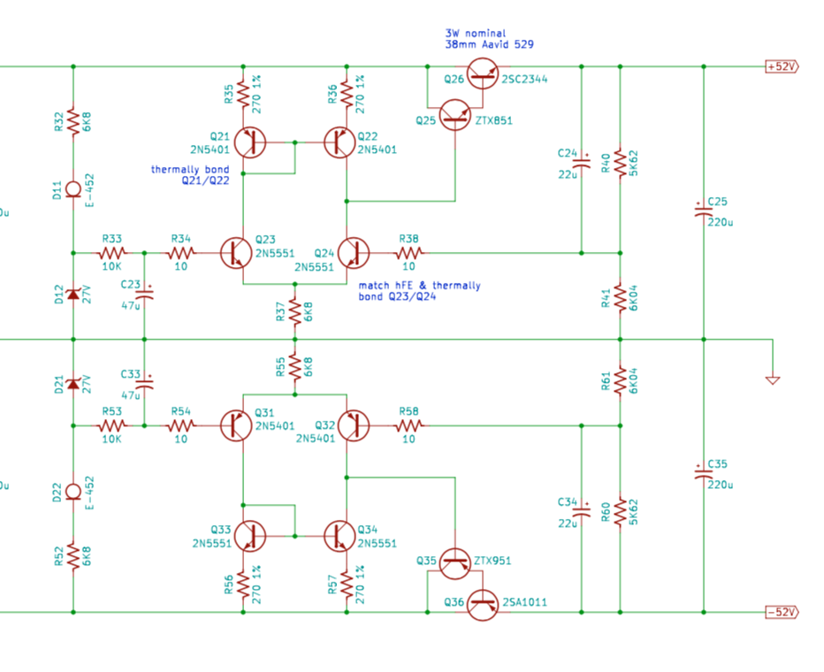
In which century do we have symmetrical electricity? Like positrons as well as electrons. Like positive cathode tubes? Some things don’t change. Which is a source of insight if you think hard enough about it.And why in the 21st century quasi complementary output
Last edited:
BTW in your psu schematic C3 & C4 should be uF.
Is this confirmed?
The BOM and board are set up for 220pF Film caps in C3, C4.
Is this confirmed?
The BOM and board are set up for 220pF Film caps in C3, C4.
No. If this is the original http://www.acoustica.org.uk/t/naim/poweramp_pix/nap reg schema.pdf
Then I am wrong.
I should have checked. I thought there was a mistake because zeners are noisy and it is common to shunt them with a large capacitance.
The BOM is correct.
If I were to design it myself I would indeed put in a bigger shunt (and even more importantly I'd put in a CCS for the zener). But I was trying to stay as true to JV's as possible.
(FWIW, here's my "clean sheet" regulator for another project, although it only handles the front-end:
If I were to design it myself I would indeed put in a bigger shunt (and even more importantly I'd put in a CCS for the zener). But I was trying to stay as true to JV's as possible.
(FWIW, here's my "clean sheet" regulator for another project, although it only handles the front-end:
Attachments
nap250 without regulator
I think what you have is a Nap200 clone, without regulator.
what are the benefits? build a set and report your impressions. i would be interested in your conclusions.
i noticed a nice bass control from the rig i built. i attribute that to the regulation. also the effortlessness i attributed to regulation. it would be interesting to hear your impression if you notice any differences.
You realise the rail voltages of NAP 140 are only 34V and NAP110 even lower? It does make a difference if they are what you intend cloning. If it's the NAP250 with 40V regulated rails you are following, don't try to use unregulated 43V supplies with the VAS transistors specified. I should add that it will work but regardless of additional heatsinking, results will be better if you switch to another clone type, such as an NCC200 clone, and follow that trail of using standard off-the-shelf parts instead.
My NAP250 really cool with DC40 volt without regulator.
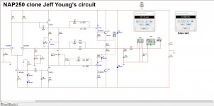
Hi Jeff I came back I fix some bug from me on post #153 and this is how the layout look like now ")
question this can work without the regulator? I see J1 and J2 and about current consumption in standby is low I got on simulation about 42mA from a 14.4mV
TP1 and TP2 that is about normal? I change P1 to 2.2K because it was drawing too much current if P1 use original value of 1K let me know when you get time
Regards
Juan
Attachments
Last edited:
Yep, silver mica would be fine.
https://www.google.com/url?sa=t&rct...s-W-Jung.pdf&usg=AOvVaw0uRmqE9ayLCqekKyUkWneO
Hi Juan,
Yes, you can regulate whatever you want. Naim regulated both the front-end and output stage on the 250, and neither on the 140. Most HackerNAP folks regulate just the front-end.
The jumpers are there to support various configurations (including single regulator for both but bi-wiring from the regulator to the amp board).
Odd that you had to change P1. Was it drawing too much current in the sim, or in real life? (If the former, I'd guess it's just some bad models in the sim.)
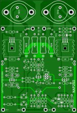
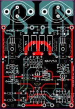
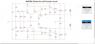
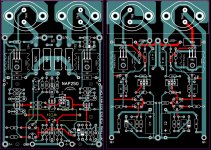
P1 with actual original value 1K got it thanks and regulation info, I spend some time redrawing your layout I mean transferring to Sprint Layout 6 I love this style of kind like vintage look so nice here is the images side by side "not done yet"
oh yes on simulation was drawing too much current got to be the simulation error yes I agree thanks Jeff
regards
Juan
oh yes on simulation was drawing too much current got to be the simulation error yes I agree thanks Jeff
regards
Juan
Attachments
- Home
- Amplifiers
- Solid State
- NAP250 clone