... the word “silvered” which gives a suggestion of quality.
That would be a perfect example of what I mean by "audiophoolery". Or that a "special" blend of dirt in a box can make a better ground.
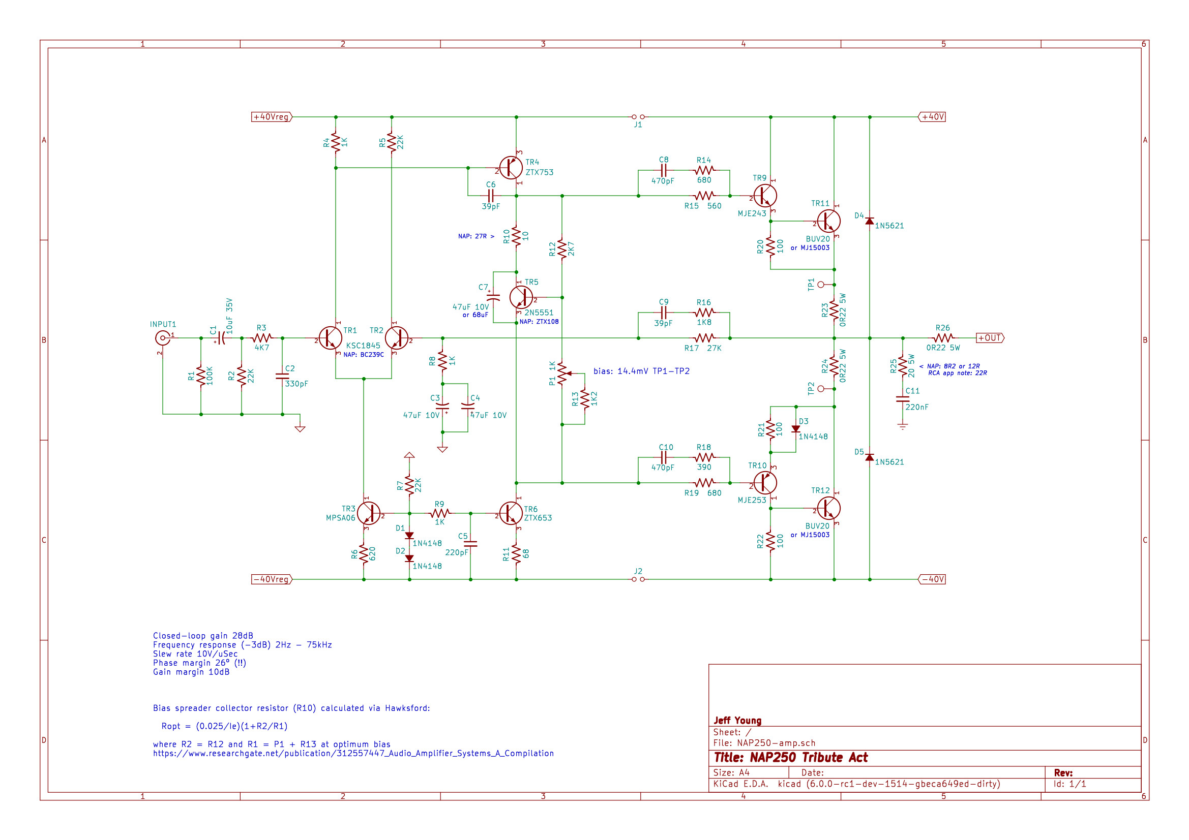
In draft 2, ... I’d put R2 the other side of R3 and make it 27k.
Oops, that's a typo. It's meant to be 22K.
A single 47uF tant in the feedback pole gives a corner at 4Hz which is probably fine, but two of them moves it down to 2Hz which is what I always shoot for when I can get there. I might go with a single 68uF though....
Admittedly it's only SPICE, but 47pF of Miller compensation oddly enough gives me a /worse/ phase margin than 39pF.
Cheers,
Jeff.
If C1, C3 & C4 are tantalums they need to be high voltage, like 25V or more. This is to do with making sure they have enough reverse voltage tolerance.
All the service kits I've seen have 6V3 caps for C3 & C4. Are those not sufficient? (The second draft board will take up to 10V for C3 & C4, and 35V for C1.)
Some options for the front-end regulation:
Differential. (This is essentially the Naim regulator without current limiting and powering only the front-end.)

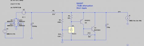
Shunt.

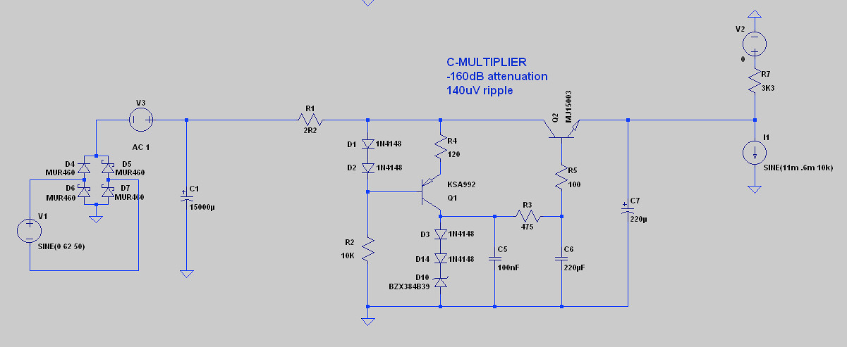
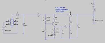
C-multiplier.
Maida.
1,200uV of ripple. Disqualified.
Jung Super Regulator.
Clearly better performance than any of the above, but gave SPICE fits trying to find the operating point. Probably over my pay-grade; disqualified.
Differential. (This is essentially the Naim regulator without current limiting and powering only the front-end.)
Shunt.
C-multiplier.
Maida.
1,200uV of ripple. Disqualified.
Jung Super Regulator.
Clearly better performance than any of the above, but gave SPICE fits trying to find the operating point. Probably over my pay-grade; disqualified.
Attachments

You were right to question, traderbam. My apologies to all, as I recall the article I read in 2015 described and was illustrated with a model based on the literal meaning of LAPT which is actually Large Area Parallel Transistor.This sounds like more Self bollocks. Have you a link? There is always an adverse affect to using multiple output devices. Capacitance matters.
Perhaps it was a misleading translation but it would have taken me a lot of time and money to follow up references. Still, it seems I should have done so at the time and not assumed the explanation was factual.
Sanken also make lesser grades of high Ft, triple diffused audio power transistors, so it was all too easy to assume that there were physical differences as great as the title suggested. Anyway, the following link is to an old thread with better known details of LAPTs posted by jacco vermuelen. Apparently, they are best described and grouped with Ring Emitter Transistors, like many other competing products considered to be multi-emitter devices.
Self's load-invariant amplifier isn't bollocks, btw. It just demonstrates that doubling the number of devices in a CFP output stage can virtually halve non-linearity of the current gain. The effect shows up most clearly with modern power devices that are already quite linear but this isn't necessarily intuitive. I'd think this is why the article was written and more recently, a PCB offered.
Jeff, If you are going down the road of isolating and separately regulating the power supply to the front end of Naim amplifiers, don't. It's sure to screw up the sound. Just ask Rensli or read his earlier posts on this topic in the NAP140 Ebay thread. I have my own catalogue of blunders with modifying Naims but some mods you read of on the net really don't improve anything and some are quite counter-productive. Good general design principles perhaps but not suitable for this type of product. Maybe their amplifier never did make it to the top shelf anyway.
Simplified, the issue is that the input stage, VAS and output stage do pass some signal between each other via the supply rails and if you sever those paths, you lose a few elements of the sound quality. If you consider Naim sound quality desirable, don't inadvertently ruin your clone by altering it in that way.
As you probably know, NAP 250 and 135 are fully regulated power supply models which already have considerably better PSRR than basic models. Of course, if you need it, regulation also offers a better safety margin with highest sensible power rating for a given pair of output transistors.
Last edited:
On the one hand, it makes logical sense to regulate the input/VAS stage. Not least because voltage variation on the supplies will vary between positive and negative output cycles, being first on the positive supply and then on the negative supply. The PSRR is not the same on both supplies. So, there is an argument to removing power supply noise at the input/VAS section. This is what Naim did recently, as I understand it, with their "Direct Regulation" thing. The original 250 didn't bother with this, as you know, but did regulate the entire power supply, separately for each amp board.
On the other hand, a regulator can cause more trouble than it solves. It is, if you like, a low bandwidth audio amplifier itself and will suffer from all the same problems. It is not easy to make a regulator better than a good capacitor from an audio amplifier point of view. An off-the-shelf regulator design is not necessarily going to make things better, just different or worse as Ian points out.
On the third hand, why not try it? This is DIY Audio after all. Have a go.
Why not arrange your board layout so that it is easy to bridge the input section and output section power supplies OR insert regulators between them?
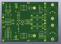
A few initial comments on your PCB layout in post 36.
First, nice looking layout. Very tidy.")
The psu pads for the input section could be located closer to the output section ones so it is easier to connect them directly (if you don't use a regulator).
Noise is important. The GND trace for C11 cuts strisght through the input section. This trace will be quite noisy, especially at HF. Naim takes the GND off at the output end of the board.
Again on noise, the LTP bases are very sensitive, especially the inverting input. So keep the copper short.
The TO3 tracks between mounting holes are a little tight to other pads and the board edge for my taste. You don't need these so thick. After all, the transistor cans will be a much lower resistance path anyhow.
Note my earlier comments about capacitors.
First, nice looking layout. Very tidy.
The psu pads for the input section could be located closer to the output section ones so it is easier to connect them directly (if you don't use a regulator).
Noise is important. The GND trace for C11 cuts strisght through the input section. This trace will be quite noisy, especially at HF. Naim takes the GND off at the output end of the board.
Again on noise, the LTP bases are very sensitive, especially the inverting input. So keep the copper short.
The TO3 tracks between mounting holes are a little tight to other pads and the board edge for my taste. You don't need these so thick. After all, the transistor cans will be a much lower resistance path anyhow.
Note my earlier comments about capacitors.
It's a matter of how much you trust a galvanized, nickel plated or even low grade stainless steel bolt, as a lifetime stable connector. Even if 1 bolt was actually fine, 2 would almost always be more reliable as the thinking goes. Since it costs nothing to have the extra track, why not include it anyway?
When Silicon Chip magazine staff were developing a blameless type amplifier kit some years ago, brass screws with shakeproof washers were used to attach spade output terminals to the prototype PCB. THD was then measured with a AP2 at around 0.001%.
On a finalized version for kits however, chrome/nickel plated screws were used and THD more than doubled. It seems unlikely but since the bolts alone conducted from the PCB copper side to the terminals on the top side, further tests proved that the plating on them was the culprit. Strange behaviour indeed, as it casts doubt on the barrel plating process as much as the actual metal:metal interface. I can only say; be wary of the source of the fasteners and avoid hard plated finishes, whatever you use for electrical connections.
On a finalized version for kits however, chrome/nickel plated screws were used and THD more than doubled. It seems unlikely but since the bolts alone conducted from the PCB copper side to the terminals on the top side, further tests proved that the plating on them was the culprit. Strange behaviour indeed, as it casts doubt on the barrel plating process as much as the actual metal:metal interface. I can only say; be wary of the source of the fasteners and avoid hard plated finishes, whatever you use for electrical connections.
Fascinating.
I must admit my fasteners knowledge comes from the days when I raced Formula Ford, which has a whole different set of constraints.
In a humid environment like Ireland, you probably also have to be wary of galvanic action. Tin, brass, copper, lead and 403 stainless are all in the middle of the scale, but aluminium and zinc are both pretty anodic while the 300 series of stainless steels and gold are pretty cathodic. Probably best not to use a 300-series stainless fastener with aluminium on a conductive joint.
In post #44 I sold the differential/Naim regulator short. I didn't specify the transistor type for the LTP so SPICE was using whatever the default NPN model is (evidently pretty wretched).
With MPSA06's the ripple drops to 30uV, making it the clear winner (performance wise) of the 3.
Borderline stability with excellent performance: sounds a bit like the amp circuit, doesn't it?
With MPSA06's the ripple drops to 30uV, making it the clear winner (performance wise) of the 3.
Borderline stability with excellent performance: sounds a bit like the amp circuit, doesn't it?
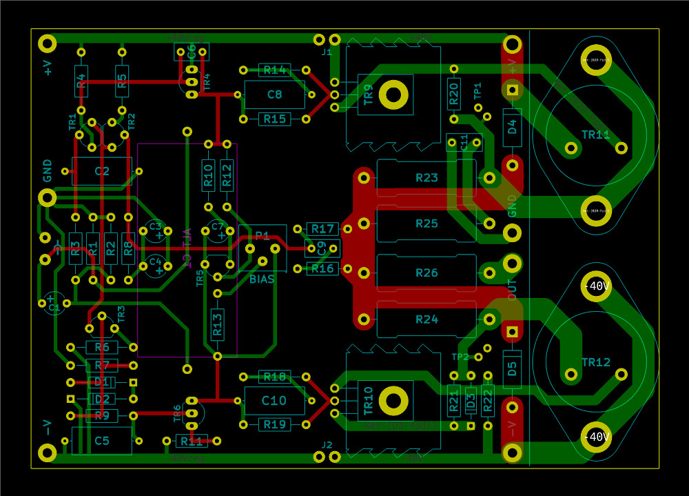
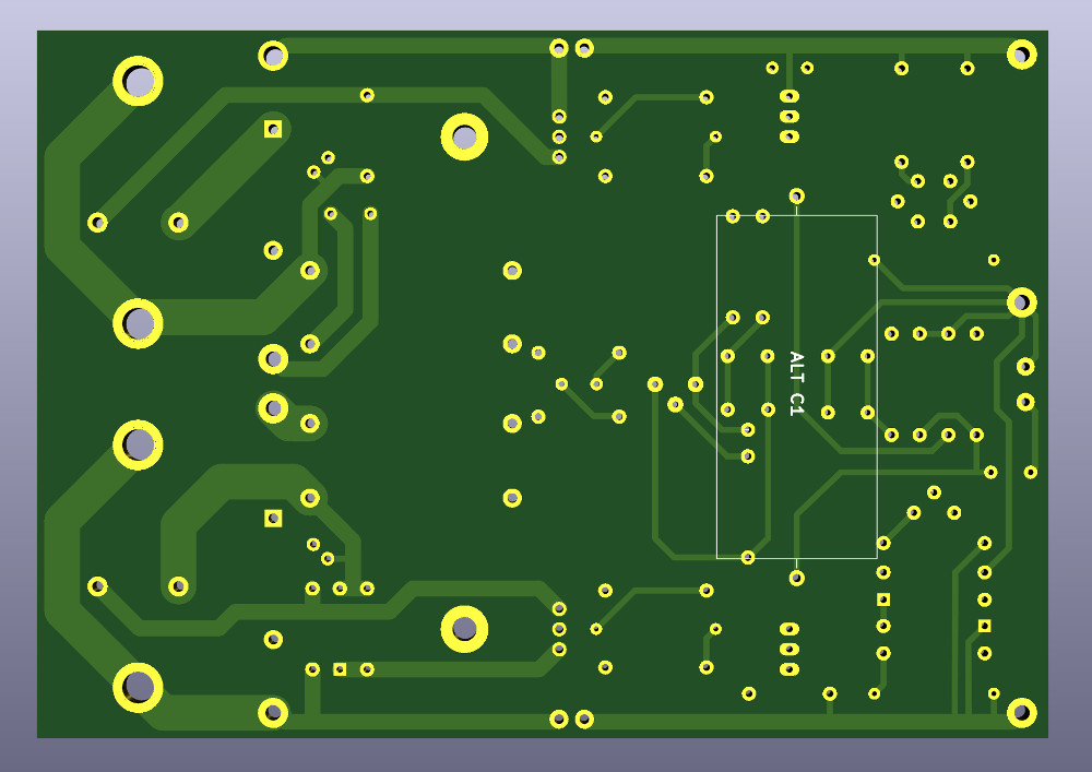
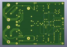
Amp PCB draft 3.
Moved Zobel ground so as not to couple with FE traces.
Made LTP slightly more compact.
Fixed input resistor value and cap polarity.
Added jumpers so that a single supply could easily be used.
Shrunk the output copper a bit to ease congestion.

Moved Zobel ground so as not to couple with FE traces.
Made LTP slightly more compact.
Fixed input resistor value and cap polarity.
Added jumpers so that a single supply could easily be used.
Shrunk the output copper a bit to ease congestion.
Attachments
TR2 base trace should be as short as possible, in the range of 1/4" or less. This is the summing junction of the amplifier, which has the full open loop gain of amplifier. Amplifier open loop gain values range from about 20,000 to 200,000.
Ref.
https://www.analog.com/media/en/training-seminars/design-handbooks/Basic-Linear-Design/Chapter12.pdf
Ref.
https://www.analog.com/media/en/training-seminars/design-handbooks/Basic-Linear-Design/Chapter12.pdf
Great link, WSJ!
Aren't those common opamp gain values, though? I think the RCA/NAP topology would be considered a "high NFB" design, and it's open loop gain is only 79dB (9,000x).
I've only played with a handful of designs so far though, so I could be wrong on either one of those.
Aren't those common opamp gain values, though? I think the RCA/NAP topology would be considered a "high NFB" design, and it's open loop gain is only 79dB (9,000x).
I've only played with a handful of designs so far though, so I could be wrong on either one of those.
The lower gain may be correct, however, a short trace at the summing junction is the best way to limit noise pickup. Just move all the components connected to the base so the trace is as short as possible. Try touching the summing junction with you finger on an amp with the power on, you will hear how much noise and hum is injected into the amp.
Last edited:
Lol, thats what i have tought all the timeI agree shortening it would limit any noise coupling.
However, I like my layouts to look like what they do. Quirky? Sure. But that's what makes the human race fascinating.
Whatever i do, i end up always drawing the pcb's
Last edited:
- Home
- Amplifiers
- Solid State
- NAP250 clone