Hi
I am working on a Tandberg 1055 and there is a what looks like a bulb market 12v 3W in line with the positive output of the power supply for the preamp section.
Can anyone explain what is the purpose of this?
and can I replace it with a standard 12v bulb?
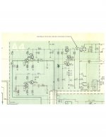
I have attached the circuit- the transistors in that section all test good-Q406/Q407 and Q405-though Q405 has a Hfe of 65-and although I found a dry joint- I am getting 36.5v into the bulb and 0v out.
I have replaced the electrolytics as I am recapping this unit.
Thanks for any assistance
Peter
I am working on a Tandberg 1055 and there is a what looks like a bulb market 12v 3W in line with the positive output of the power supply for the preamp section.
Can anyone explain what is the purpose of this?
and can I replace it with a standard 12v bulb?
I have attached the circuit- the transistors in that section all test good-Q406/Q407 and Q405-though Q405 has a Hfe of 65-and although I found a dry joint- I am getting 36.5v into the bulb and 0v out.
I have replaced the electrolytics as I am recapping this unit.
Thanks for any assistance
Peter
Attachments
can I replace it with a standard 12v bulb?
Those fuse lamp bulbs are cheap, so try to get an exact replacement, 3W/12VDC/250mA.
The bulb should be marked with a mfr part number. Is it for a 3AG socket?
Last edited:
It's there to act as a resettable fuse. If you can't find an exact replacement bulb, you could consider fitting the modern equivalent Polyfuse:
Resettable fuse - Wikipedia
Resettable fuse - Wikipedia
@dhaen- thanks for explaining this, I was thinking miniature dim bulb tester- so it acts as a current limiter- though I had not come across this technique before.
I was also wondering why 12v, as the voltage at this part of the circuit is 40v (36.5 actual)- so should I get a 12v polyfuse, or higher voltage? -and current I am guessing will come from the rating on the bulb?
I was also wondering why 12v, as the voltage at this part of the circuit is 40v (36.5 actual)- so should I get a 12v polyfuse, or higher voltage? -and current I am guessing will come from the rating on the bulb?
Polyfuses are rated by current, not voltage, but you can forget that for the purpose of this repair.
On further study of your circuit - and your comment about the voltage on those point, I realise that I was wrong. In fact I think the bulb is meant to glow in normal use so a bulb of the correct ratings is necessary.
Sorry for the temporary diversion from reality!
On further study of your circuit - and your comment about the voltage on those point, I realise that I was wrong. In fact I think the bulb is meant to glow in normal use so a bulb of the correct ratings is necessary.
Sorry for the temporary diversion from reality!
Hi Pwdiya12,
If I understand it correctly, it also starts the power supply up slowly. When the bulb is cold, it has a high resistance and so limits the current. As it gets hot, its resistance drops and it acts as a low value resistor. Therefore it acts as a current surge limiter. The same principle is used on my Studer C37 to limit the motor current using a 250V 60 watt bulb.")
Old school engineering in action.
Cheers
Mike
If I understand it correctly, it also starts the power supply up slowly. When the bulb is cold, it has a high resistance and so limits the current. As it gets hot, its resistance drops and it acts as a low value resistor. Therefore it acts as a current surge limiter. The same principle is used on my Studer C37 to limit the motor current using a 250V 60 watt bulb.
Old school engineering in action.
Cheers
Mike
@fredbloggstwo- thanks for this- the bulb is in series with the 25v pre amp/tuner power supply (which is the fault I am currently chasing)- so as this comes up gradually then there will be no initial turn on "thump"- so a neat trick to avoid putting in a relay perhaps?
The amp itself does not appear to have any protection circuit, and thus no relay.
A cunning plan indeed
Thanks for all the assistance- I will report back when I have replaced the bulb
Best Regards
Peter
The amp itself does not appear to have any protection circuit, and thus no relay.
A cunning plan indeed
Thanks for all the assistance- I will report back when I have replaced the bulb
Best Regards
Peter
Don't second-guess Tandburg. Use the specified incandescent lamp, 12V 3W.
It is not a "self-resetting fuse"--- it just blows if there is a short on the 25V line. So get extra lamps, disconnect as many 25V feeds as possible, and reconnect them one at a time until you find the shorted feed. (Alternatively a 100 Ohms 10 Watt resistor-- it may not come to full 25V when all is well but will go to Zero harmlessly as long as there is a short.)
> If I understand it correctly, it also starts the power supply up slowly. When the bulb is cold, it has a high resistance and so limits the current. As it gets hot, its resistance drops and it acts as a low value resistor. Therefore it acts as a current surge limiter.
No. Cold lamp is low resistance. The Studer is a tape deck? Tape reel motors need a good jolt of current to kill the inertia of the reels, tapering off as tape comes to speed.
Lamp holders used to be commonplace. You can probably find what you need at a surplus store. If bad comes to worse, you can always solder the lamp in directly.
I'm with PRR that the bulb is used as a current control device, not as a fuse. With the cold resistance of a bulb being much lower (orders of magnitude lower) than the hot resistance, it's not an inrush limiter. It's also on the wrong side of the main supply cap (C413 - 1000 uF) for that.
Tom
I'm with PRR that the bulb is used as a current control device, not as a fuse. With the cold resistance of a bulb being much lower (orders of magnitude lower) than the hot resistance, it's not an inrush limiter. It's also on the wrong side of the main supply cap (C413 - 1000 uF) for that.
Tom
3 Watt - Clear - T3.25 - Wedge Base - Bulbrite 715503
Wedge-base sockets hard to find, and shipping is silly. Gently bend-out the U-leads just enough to get sandpaper on both sides. Polish the leads. Tin with solder. Attach insulated leads as needed to get to where it connects. Use two pieces of shrink-tube to insulate against case contact.
Get several; as spares, but also because bending the U-leads may crack the seal.
[...] a quick kiss of the soldering iron and all was back to normal
I don't think I'll ever look at my soldering iron the same way again. Thanks!
Tom
- Status
- This old topic is closed. If you want to reopen this topic, contact a moderator using the "Report Post" button.
- Home
- Amplifiers
- Solid State
- Tandberg mystery bulb in power supply