I'm trying to figure out feedback compensation so I'm working through a few examples while leafing furiously through Cordell. But I'm a bit stuck.
Given the following front-end:
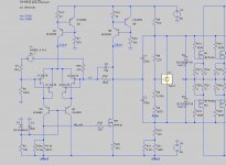
Closed-loop gain is 20dB.
If I disconnect the NFB (by deleting the wire under "0V") I get a gain of 67dB. That's my open-loop gain, right?
How do I calculate the unity-gain frequency (where open-loop gain = closed-loop gain)?
If I examine the open-loop gain curve, it crosses 20dB (the closed-loop gain value) at 560kHz. Is that my unity-gain frequency? Or do I have to somehow do that with feedback connected?
Also, if I plot the output of the LTP (with NFB & Miller compensation connected), I get a big hump centred on the same 560kHz:
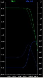
What's that?
Thanks for any insight,
Jeff.
Given the following front-end:

Closed-loop gain is 20dB.
If I disconnect the NFB (by deleting the wire under "0V") I get a gain of 67dB. That's my open-loop gain, right?
How do I calculate the unity-gain frequency (where open-loop gain = closed-loop gain)?
If I examine the open-loop gain curve, it crosses 20dB (the closed-loop gain value) at 560kHz. Is that my unity-gain frequency? Or do I have to somehow do that with feedback connected?
Also, if I plot the output of the LTP (with NFB & Miller compensation connected), I get a big hump centred on the same 560kHz:

What's that?
Thanks for any insight,
Jeff.
How do I calculate the unity-gain frequency... ... Also, if I plot the output of the LTP (with NFB & Miller compensation connected),
Hi Jeff
The best way to check the stability is to simulate, which can do much better than a simple hand calculation. There are examples in the LTspice folder, the best method is called a "Tian" probe. If you search my posts for this keyword I have discussed it a fair bit, also I attached an improved Tian probe that may be useful once you have a bit of experience.
I saw you also posted in the Pass forum, before too much discussion I would like to clarify nomenclature. By "Miller compensation" do you mean C4? That is more like a phase lead capacitor, not quite standard Miller. Your stability is ok but could definitely be improved.
Best wishes
David
Last edited:
Unity gain frequency is where the gain reaches unity, or would reach unity when extrapolated from mid-band gain assuming first-order rolloff. Your circuit has an open-loop UGF and a closed-loop UGF; if it really has a first-order rolloff then they will be at the same point.
The point where the open-loop gain equals the (mid-band) close loop gain is not necessarily the UGF. It is the point where closed-loop gain is 3dB down, so 17dB instead of 20dB.
If you have a first-order rolloff and open-loop gain is 20dB at 560kHz then UGF is 5.6MHz.
The big hump you see at an intermediate point is not unusual. This can sometimes catch people out when calculating signal headroom.
Thanks, guys!
Yes, by Miller compensation I meant C4. I thought the difference between it and the Miller compensation Cordell presents was just that it's enclosing both the LTP and VAS, rather than only the VAS. I'll have to google "phase lead capacitor" along with "Tian probe".
@DF96, so when Cordell says a Bode plot shows the amplifier in "idealized form", does he essentially mean "assuming a first-order rolloff"?
Thanks, Jan, I've made that change. (I used 10MegH to keep from getting any roll-off at the bottom end.)
I haven't yet studied up on all those links, but I did glean enough to take another approach. This is a GIMP merge of the open-loop and closed-loop SPICE plots:
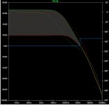
I've coloured the NFB gain in grey.
Normally I need to control excess phase up to the point where the NFB reaches 0, right? In this case, interestingly, the blue line appears to show that the amp is bandwidth limited (just) before the NFB reaches 0?
If I then run the blue line up to the excess phase angle it shows that I've got about 45º of phase margin?
Is that a correct reading of these particular tea leaves?
Thanks again,
Jeff.
I haven't yet studied up on all those links, but I did glean enough to take another approach. This is a GIMP merge of the open-loop and closed-loop SPICE plots:

I've coloured the NFB gain in grey.
Normally I need to control excess phase up to the point where the NFB reaches 0, right? In this case, interestingly, the blue line appears to show that the amp is bandwidth limited (just) before the NFB reaches 0?
If I then run the blue line up to the excess phase angle it shows that I've got about 45º of phase margin?
Is that a correct reading of these particular tea leaves?
Thanks again,
Jeff.
The open-loop/green curves remove both the NFB and the phase lead compensation (what I think I was erroneously calling the Miller compensation earlier).
If I remove just the phase lead compensation, then the closed-loop/red curve shows essentially the same phase margin as the open-loop/green. (And yes, those are over 180º.)
If I remove just the phase lead compensation, then the closed-loop/red curve shows essentially the same phase margin as the open-loop/green. (And yes, those are over 180º.)
I think I figured it out the open-loop/closed-loop part.
You run the open-loop curves first to see if you have a problem (ie: before adding any compensation). The phase lag has already crossed 180º by the time we get to unity:
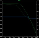
Close the loop and sure enough, it looks ugly:
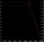
Now add the phase lead compensation to the closed loop (this time with a bit more capacitance then I used a few posts ago):
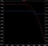
This shows 60+º phase margin, which I think is good.
Now on to gain margin....
You run the open-loop curves first to see if you have a problem (ie: before adding any compensation). The phase lag has already crossed 180º by the time we get to unity:

Close the loop and sure enough, it looks ugly:

Now add the phase lead compensation to the closed loop (this time with a bit more capacitance then I used a few posts ago):

This shows 60+º phase margin, which I think is good.
Now on to gain margin....
RobLK posted a link on the other thread to a LT video on how to model open-loop gain. Essentially you ground the input, break the loop with a 0V voltage source, and then inject your AC analysis through that voltage source:
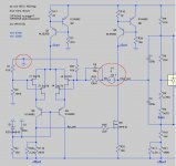
You then plot V(LTP_out)/V(FB) and you can look at the response with compensation changes.
Here are the responses with 10p, 15p and 20p for C4:
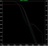
Phase margins are 79º, 77º and 75º. Fairly minor differences, as are the bandwidth differences.
Oh, and gobs of gain margin (44dB w/ 10pF and still 38 dB w/ 20pF).

You then plot V(LTP_out)/V(FB) and you can look at the response with compensation changes.
Here are the responses with 10p, 15p and 20p for C4:

Phase margins are 79º, 77º and 75º. Fairly minor differences, as are the bandwidth differences.
Oh, and gobs of gain margin (44dB w/ 10pF and still 38 dB w/ 20pF).
- Status
- This old topic is closed. If you want to reopen this topic, contact a moderator using the "Report Post" button.
- Home
- Amplifiers
- Solid State
- How to calculate unity-gain frequency?