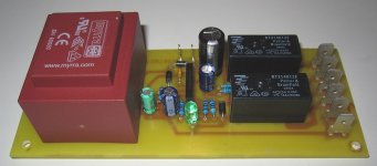
Well, the board says AC. But I do not see a rectifier. Which means it maybe needs DC. And wrong polarity WILL blow-up the regulator.
If I could see the bottom of the board, how the power terminals connect to the first filter capacitor and the LM7812 regulator, I could guess a "most likely" polarity. But I do not trust ten-dollar products.
Many many thanks for your time helping me.
Meanwhile, when i receive this module. I will post pictures from the bottom of the board, and i hope you can help me.
Best regards.
Well, the board says AC. But I do not see a rectifier. Which means it maybe needs DC. And wrong polarity WILL blow-up the regulator.
If I could see the bottom of the board, how the power terminals connect to the first filter capacitor and the LM7812 regulator, I could guess a "most likely" polarity. But I do not trust ten-dollar products.
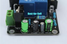
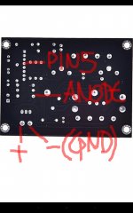
I find on the web an picture from the bottom of the board, you can see and help me to find what is the positive and negative of the power terminals connect ?
Best regards.
Attachments
Last edited:
Well, the board says AC. But I do not see a rectifier. Which means it maybe needs DC. And wrong polarity WILL blow-up the regulator.
If I could see the bottom of the board, how the power terminals connect to the first filter capacitor and the LM7812 regulator, I could guess a "most likely" polarity. But I do not trust ten-dollar products.
Other picture from the bottom of the board.
Best regards.
Attachments
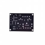
I find on the web an picture from the bottom of the board, you can see and help me to find what is the positive and negative of the power terminals connect ?
Best regards.
Hi Jorgesilva,
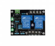
Theses boards only require AC power from the green connector, there are two diodes (not a full bridge here) close to the green connector that will convert AC into DC to power the module. I have built a very similar circuit, mine carries a small transformer.
Cheers,
Jacques
Attachments
Hi Jorgesilva,
Theses boards only require AC power from the green connector, there are two diodes (not a full bridge here) close to the green connector that will convert AC into DC to power the module. I have built a very similar circuit, mine carries a small transformer.
Cheers,
Jacques
Hi Jacques, i hope you have an nice day.
If i understand, i can connect DC voltage direct into this board from my DC power supply, right?
You can explain me what is the positive and the negative in the green connectors terminal for i can wiring this correctly?
I hope you can help me on this.
Best regards.
Hi again Jorgesilva,
No, you don't want to connect DC. Just AC as indicated on the board. The reason is simple. the uPC module has several distinct functions. The most important one is to protect your speakers from DC when your amplifier blows up. There are two more functions: 1. avoid thump when your turn on the amp using a small delay in triggering the relays. 2. avoid thump when you turn off your amp. This last option will detect the lack of AC immediately and switch off the relays. If you use DC, there are usually big electrolytics in your PSU which store a lot of energy. In that case the relays will turn off too late and the thump will occur.
You can also read the uPC1237 spec sheet for more info.
Cheers,
Jacques
Last edited:
Hi again Jorgesilva,
No, you don't want to connect DC. Just AC as indicated on the board. The reason is simple. the uPC module has several distinct functions. The most important one is to protect your speakers from DC when your amplifier blows up. There are two more functions: 1. avoid thump when your turn on the amp using a small delay in triggering the relays. 2. avoid thump when you turn off your amp. This last option will detect the lack of AC immediately and switch off the relays. If you use DC, there are usually big electrolytics in your PSU which store a lot of energy. In that case the relays will turn off too late and the thump will occur.
You can also read the uPC1237 spec sheet for more info.
Cheers,
Jacques
Hi Jacques. If i understand, i cannot power this module with DC voltage, and i need other module can support DC voltage right? Or buy a module with transformer for i can hook 220v directly on it, right?
I see other modules and support DC voltage but the relay os only rated for 10A.
My amplifier board is an TDA7498E, i supply 36v DC from my power supply module.
My speakers is rated to 100W - 4Ohm.
It's fine use relays rated for 10A or 30A is much better?
Best regards.
Last edited:
This module is ALSO works if powered by DC (need to determine voltage 1st!) instead of AC.
But if you do this, AC sensing function of course won't work correctly - this feature is used
to disconnect speakers immediately once AC voltage disappears.
As Jacques said - you MAY have a thump in the speaker when powering off. But it's not very likely.
Thump is more likely when powering ON - this will still be prevented, I think.
If it's fine with you, can you can use DC to power it.
Since it's using LM7812, and rectifier diode will drop 0.7V, most likely you need DC voltage over 16V.
Since it's using relays, you will need at least 200mA or more.
You just need to find out which AC input terminal is ground (-), and which one is rectified (+).
I'm using uPC1237 powered by DC in couple of amps, and everything is fine.
Last edited:
This module is ALSO works if powered by DC (need to determine voltage 1st!) instead of AC.
But if you do this, AC sensing function of course won't work correctly - this feature is used
to disconnect speakers immediately once AC voltage disappears.
As Jacques said - you MAY have a thump in the speaker when powering off. But it's not very likely.
Thump is more likely when powering ON - this will still be prevented, I think.
If it's fine with you, can you can use DC to power it.
Since it's using LM7812, and rectifier diode will drop 0.7V, most likely you need DC voltage over 16V.
Since it's using relays, you will need at least 200mA or more.
You just need to find out which AC input terminal is ground (-), and which one is rectified (+).
I'm using uPC1237 powered by DC in couple of amps, and everything is fine.
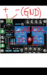
How can i find the positive (+) and negative (ground/-) on this module? Can you help me through this pictures?
How can i find the positive (+) and negative (ground/-) on this module? Can you help me through this pictures?
You need to start with AC terminal.
2 pins (screws).
One of them will lead, directly or indirectly to a DIODE (to anode).
You need to identify the diode on the PCB, and check which pin from AC terminal, leads to it.
Follow the tracks on the PCB, use ohmometer to check what's connected to what.
Cathode of the diode will be connected sooner or later to LM7812 regulator.
2nd pin from AC terminal will lead to the GROUND - which must be connected
to pin 5 on the chip upc1237.
Last edited:
You need to start with AC terminal.
2 pins (screws).
One of them will lead, directly or indirectly to a DIODE (to anode).
You need to identify the diode on the PCB, and check which pin from AC terminal, leads to it.
Follow the tracks on the PCB, use ohmometer to check what's connected to what.
Cathode of the diode will be connected sooner or later to LM7812 regulator.
2nd pin from AC terminal will lead to the GROUND - which must be connected
to pin 5 on the chip upc1237.
I trace the connector terminal AC and fix me if i'm wrong.
See if i'm correct on my schematic, it's ok?
If i'm correct, next, i will supply this module use a DC step down converter between my power supply module 36v 5A and this speaker protection module.
Best regards.
Attachments
Last edited:
I trace the connector terminal AC and fix me if i'm wrong.
See if i'm correct on my schematic, it's ok?
Best regards.
Looks correct.
What DC voltage are you planning to use to power this?
36v might be too much - check voltage ratings on electrolytic capacitors around LM7812.
One of them gonna have higher voltage than others... This cap will be connected to cathode of the diode, and the ground.
Do not go higher than rated volatege.
LM7812 max input voltage is 35V. I would recommend staying well below 30V.
It's gonna run hot..
Last edited:
Looks correct.
Thanks for helping me find the correctly way to wiring this module without burn it.
I will supply this module use a DC step down converter between my power supply module DC 36v 5A and this speaker protection module, but i only plan use between 12v and 15v, for this reason i use my step down converter.
Can i use this way, right?
I hope don't burn this when i power up my amplifier.
Last edited:
Thanks for helping me find the correctly way to wiring this module without an burn it.
I will supply this module use a DC step down converter between my power supply module 36v 5A and this speaker protection module.
I hope don't burn this when i power up my amplifier.
What DC voltage are you planning to use to power this?
36v might be too much - check voltage ratings on electrolytic capacitors around LM7812.
One of them gonna have higher voltage than others... This cap will be connected to cathode of the diode, and the ground.
Do not go higher than rated volatege.
LM7812 max input voltage is 35V. I would recommend staying well below 30V.
It's gonna run hot..
Thanks for helping me find the correctly way to wiring this module without burn it.
I will supply this module use a DC step down converter between my power supply module DC 36v 5A and this speaker protection module, but i only plan use between 12v and 15v, for this reason i use my step down converter.
Can i use this way, right?
I hope don't burn this when i power up my amplifier.
Your DC VCC must be minimum around 15V to make LM7812 work correctly
(check the datasheet)...
https://www.ti.com/lit/ds/symlink/l...ll-mousermode-df-pf-null-wwe&ts=1589391635135
I've seen/tried modules with 7812 powered by less than 12V,
and LM was passing this voltage trough, so it kind of worked,
but you don't want to do this with speaker protection
")
The NEC datasheet says VCC 25V to 60 V stable operation.
How do these Chinese making it work at 12 VDC?
regards
prasi
PIN 8 (Vcc) of the upc chip takes max 8V.
The example schematic they show in the datasheet is powered via resistor.
Now, depending on that resistor, the board might work with 12V.
- Home
- Amplifiers
- Solid State
- UPC1237 Speaker protection board: Current requirements