Hi folks
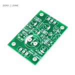
I picked up a pair of these tiny 'Atom BR' boards, supposedly it's the JLH 1969 design redrawn.
The boards I have are labelled Zero Zone MM-2 NPN-1969, there is also a PNP version too, but I bought the NPN ones.
I can find no info on these boards, no build threads, nada.
The board is marked to use 2SC2705 and 2SA970 trannies, I have substituted 2SC1570 and 2SA929, working pulls from a 1983 Sharp amp I scrapped.
For the main output trannies I have used Fairchild E13009K, which is their version of the Motorola MJE13009, the ebay listing suggests Sanken 2SA1216, but most of those are fakes these days, I'm hoping the Fairchilds are real, I got them from a UK supplier.
However, I can't complete stuffing the boards as the values of some components are not marked - resistors R1 and capacitors C1, C2 and C3.
Has anyone built this design before and knows the correct values for these parts?
Attachments
What do you need to know? They are essentially to the original designs and only vary in their adaption to TO3P lead spacing, polarity and layout. There are many JLH 69 boards but their differences are few, electrically speaking. Most vary in the space provided for monster coupling capacitors, onboard power semis and power supplies, regulated or cap. multiplier power supplies.
This kit though, is absolutely minimal and needs to be mounted directly to substantial heatsinks, via its power transistor leads. It's a very convenient and easy assembly method but it's probably where you also begin to like or loathe it as a reliable class A (i.e. hot amplifier) construction method.
This kit though, is absolutely minimal and needs to be mounted directly to substantial heatsinks, via its power transistor leads. It's a very convenient and easy assembly method but it's probably where you also begin to like or loathe it as a reliable class A (i.e. hot amplifier) construction method.
BTW, MJE1300X transistors are power switching devices - a good idea that was exploited in early class AB designs with plenty of feedback but there's not much merit for class A applications. Even if ZeroZone's parts were fakes or off-spec (as advertised, mine had been pulled from old gear) they still should work fine in the 10W version.
Hi Ian
I need to know:
1. What values to use for R1, C1, C2 and C3
2. If any changes to the values of components are required to account for using 2SC1570 and 2SA929 trannies instead of 2SC2705 and 2SA970.
3. If using E13009K output trannies means some changes to values of other components required?
4. PSU - I have built a few linear regulated supplies using L78xx and L79xx, and have just built a couple of LT1083 based regulated supplies too, but for this JLH 1969 build, I am wondering if something better, i.e. lower noise, less ripple, would be advisable. If so, what design to go for - something discrete?
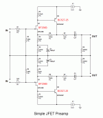
5. Preamp - to use as a front end to drive these JLH boards, what sort of preamp would be best? I read that a preamp with quite a bit of gain then limiting the JLH power section to a gain of 2 is a good way to go rather than using a unity gain buffer type preamp like the B1. I already have this simple JFET preamp stage I built a while back, if it's suitable:

6. Voltage/Current - all my components are good for 35V or more, and I have some 25v, 1A output toroidals, so I was thinking I'd run the JLH boards on 25v minus whatever the dropout of the regulator I chose is, so around 23-24v. Can I add some simple circuitry to limit current draw of the amps to 1A, which is the max the trafo will do. I could then use an LT1086 regulator (1.5A rated) based linear supply and I happen to have the LT1086 parts already.
I need to know:
1. What values to use for R1, C1, C2 and C3
2. If any changes to the values of components are required to account for using 2SC1570 and 2SA929 trannies instead of 2SC2705 and 2SA970.
3. If using E13009K output trannies means some changes to values of other components required?
4. PSU - I have built a few linear regulated supplies using L78xx and L79xx, and have just built a couple of LT1083 based regulated supplies too, but for this JLH 1969 build, I am wondering if something better, i.e. lower noise, less ripple, would be advisable. If so, what design to go for - something discrete?
5. Preamp - to use as a front end to drive these JLH boards, what sort of preamp would be best? I read that a preamp with quite a bit of gain then limiting the JLH power section to a gain of 2 is a good way to go rather than using a unity gain buffer type preamp like the B1. I already have this simple JFET preamp stage I built a while back, if it's suitable:
6. Voltage/Current - all my components are good for 35V or more, and I have some 25v, 1A output toroidals, so I was thinking I'd run the JLH boards on 25v minus whatever the dropout of the regulator I chose is, so around 23-24v. Can I add some simple circuitry to limit current draw of the amps to 1A, which is the max the trafo will do. I could then use an LT1086 regulator (1.5A rated) based linear supply and I happen to have the LT1086 parts already.
Attachments
BTW, MJE1300X transistors are power switching devices - a good idea that was exploited in early class AB designs with plenty of feedback but there's not much merit for class A applications. Even if ZeroZone's parts were fakes or off-spec (as advertised, mine had been pulled from old gear) they still should work fine in the 10W version.
I didn't buy kits, just the plain PCBs, I bought the Fairchild E13009K trannies separately, from a UK supplier, I hope they are real, but as you say, even not-so-kosher ones should be okay in a measly 10w amp hopefully.
I would not substitute components unless there were good reasons because you can buy those parts as generics quite cheaply and they work fine. If you haven't already determined what components will also work well, its a good reason for buying and trying the kit as it comes, first.
Check TCAAS, Geoff Moss's Class A amplifier site archive for the original JLH'69 articles, further designs and modifications, recommendations for power supplies, proven parts substitutes and discussion plus a whole lot more. The Class-A Amplifier Site
The only transistor that causes much concern is the splitter/driver transistor. The others are mostly a matter of convenience once the basic specs are met. There's really nothing inadequate about 2N3906 or 2N3055 grade transistors in this application and I'm just as happy with my original spec. JLH'69 as later builds that were tarted up with newer semis and expensive overkill components. Your board shows 2SC2705 but many modern, fast and low power driver transistors will also work fine. I used 2SD669A after comparing at least 8 different transistors IIRC, only because it sounded good to me and ran cool when driving modern power transistors. 2SD667A is the TO92L package version, like 2SC2705
Cheers Ian.
I've read the original 1969 article and the design notes several times, but my confusion stems from the fact that the Zero Zone board is different in how it chooses to label the components, making it hard for me to figure out what is what from comparing text to actual item. For instance, it took me a while to figure out which cap on the board is which, such as identifying C1 on the board as being the input coupling cap. In the original layout this is a 0.5uF polypropylene, but in the design notes JLH suggests increasing this value to in the range 1-2.2uF.
I was just hoping someone else has experience of building working amps using this particular variant of the JLH 1969 design and could share some useful tips as a result.
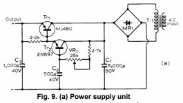
Here is the JLH design for a PSU for the 1969 amp:

But reading around, it seems that a capacitance multiplier regulated circuit is the way to go for a low power class A amp.
According to Elliot Sound Products pages, which I found very useful on class A amp design, there are two approaches, firstly using a pair of BJTs:

Secondly, using a single MOSFET:

I'm tempted to build a pair of the MOSFET version, as I already have all the needed parts. However the ESP page says this:
Hmm, so should I go for the BJT version instead, which means buying parts, or just build the MOSFET version and try it?
But reading around, it seems that a capacitance multiplier regulated circuit is the way to go for a low power class A amp.
According to Elliot Sound Products pages, which I found very useful on class A amp design, there are two approaches, firstly using a pair of BJTs:
Secondly, using a single MOSFET:
I'm tempted to build a pair of the MOSFET version, as I already have all the needed parts. However the ESP page says this:
"A sample circuit is shown above. The time constants of the filter network are identical to those shown in the other examples, and hum attenuation is improved by around 10dB - but only if the load current is constant. As noted, the hum breakthrough when transient loads are applied is far worse than a bipolar version (by at least 20dB), and it lasts longer as well (around 500ms for the MOSFET, less than 200ms for the bipolar transistor version). These figures depend on the load current, amount of current change, rate of change (etc.), and should be considered as representative only.
Overall, the MOSFET version is interesting, and it may well be useful for providing a very low noise unregulated supply. However, it performs badly if the load current isn't constant, and it also dissipates more power for a given output current than an equivalent circuit using bipolar transistors."
Hmm, so should I go for the BJT version instead, which means buying parts, or just build the MOSFET version and try it?
Attachments
The supplied parts themselves are the key to easy assembly because there is seldom any reliable documentation with Chinese kits or PCBs anyway. I guess translation and printing requirements for the export market would probably not be viable. For their local market, the Chinese style DIY kit assembly method of just following the pictures on their DIY sites seems to work fine. These kits and their PCBs though, are clearly intended to use odd or exotic parts and over the top values for JLH's 1969 design, as supplied in the kits. Still, this is clearly the intent of the ZeroZone kit PCBs we both have.
Referring to PCB IDs on PNP V1.0 boards (not much different to the NPN versions and use similar part IDs):
- R1 is an addition - a 1/4W carbon composition resistor of 2.7R in series with C1, perhaps for a sound effect. There is another of these, 2.7k value, located above the input connector. JLH numbers it R3 on his schematic. Note; those I received have drifted high by 10 - 30%, as we expect with NOS composition resistors.
- C1 is the input cap - 47 uF Nichicon muse electrolytic (bipolar) was supplied in all my kits - massively oversized.
- C2 is a polyester film cap, 1nF 400V, to lower the high frequency impedance of the output cap. (a Nichicon KG 3,300uF 25V, central in the PCB).
- C3 and C4 are Panasonic FC, 35V 560uF
-220uF caps are as marked, Elna Cerafine 16V
If you want confirmation for other parts choices, you can try kitseller's sites like this one and read the descriptions. Unfortunately, the pics of the components supplied are poor and the Chinglish text may be a problem. You may find better with more searching though. searchingtAliexpress.com : Buy Atom BR Version PNP W0302 JLH1969 Single ended Class A power amplifier DIY kit (2 channel) from Reliable amplifier diy suppliers on ASYPDZSW Store

After studying the design notes, I ended up using these parts:
C1 - 2uF Russian MGBO PIO bypassed by Evox MMK 0.1uF
C2 - Rubycon YK series 1000uF 50v bypassed by Evox MMK 0.1uF
C2 - Rubycon YK series 1000uF 50v bypassed by Evox MMK 0.1uF
(there are two positions labelled C2...)
C3 - 0.33uF Polypropylene
R1 - 100R 1W metal oxide
The positions with values marked on the board I filled with a pair of Rubycon YXF series 220uF 35v and a BHC ALT20A 2200uF 40v, all three bypassed by Evox MMK 0.1uF.
I assume your parts numbers refer to the NPN type Zero Zone PCB you plan to use.
Is that also a V1.0 board? Mine is numbered as per the the PNP version. i.e C1,C2,C3,C4 plus 2 x 220uf supply bypass caps and the output cap. I would have thought that the V reference number would change with each revision but I guess we don't know what the designer or even the particular seller were thinking.
One comment on your selection of the bootstrap capacitor (C1 of the original schematic) is I think that 1,000 uF is too much. Not all electrolytic caps are used for smoothing and filtering DC where some excess capacitance is usually desirable. This is a different application and whilst you can usually reduce distortion a little with a larger cap, that doesn't do much for sound quality, where a little more even harmonic distortion can be a good thing, since the JLH'69 is renowned for it. I would follow closer to JLH's design and fit no more than 470uF if you typically use 6-8 ohm speakers.
Yes, I have the NPN version of the Zero Zone board, no version number marked on it.
In the Design Notes, it says you can use upto 1000uF but 470uF might be better. I happened to have 1000uF caps and no 470uF, so I went for the 1000uF. I can always change them at a later date if needed.
In the Design Notes, it says you can use upto 1000uF but 470uF might be better. I happened to have 1000uF caps and no 470uF, so I went for the 1000uF. I can always change them at a later date if needed.
- Status
- This old topic is closed. If you want to reopen this topic, contact a moderator using the "Report Post" button.
- Home
- Amplifiers
- Solid State
- JLH 1969 'Atom BR' version