Mark, you make a really good point. The original intention of this thread was to sort out a bad hum, which turns out was a loose fuse holder clip on the ps filter board. That was done, and it made sense to simply replace the four electrolytic caps and two trimmers on each output board. Some of the trimmers are out of spec.
If I knew for certain that I'd keep the amp a long time, or long enough I didn't care about resale value, I'd move forward with mods. I'll sleep on it, but at the very least, I'll order the caps and trimmers tomorrow. I appreciate you reeling it in for me, and of course to KC, and phase, your help has given me some things to think about.
If I knew for certain that I'd keep the amp a long time, or long enough I didn't care about resale value, I'd move forward with mods. I'll sleep on it, but at the very least, I'll order the caps and trimmers tomorrow. I appreciate you reeling it in for me, and of course to KC, and phase, your help has given me some things to think about.
If you really care only about resale value, you wouldn’t be spending a dime on parts at this point, especially with the possibility of selling in the near future. You could just put the parts back in and it should likely continue to operate for years to come.
I just took apart a 40 year old amplifier which has never missed a beat, and replaced nearly all of the electrolytic parts inside. All the old parts measured fine for advertised values. I did observe the circuit while doing this but it didn’t change anything I was planning. I have realized that after some 20 years of ownership that I will probably have this one around for a while and should make the move to improve it a bit so it is nice to listen to as a back up.
I just took apart a 40 year old amplifier which has never missed a beat, and replaced nearly all of the electrolytic parts inside. All the old parts measured fine for advertised values. I did observe the circuit while doing this but it didn’t change anything I was planning. I have realized that after some 20 years of ownership that I will probably have this one around for a while and should make the move to improve it a bit so it is nice to listen to as a back up.
Not necessarily. Three of the four trimmers I removed are way out of spec and need to be replaced. The electrolytic caps I pulled don't all measure in spec either. If I simply replace with new caps, same values ... from my experience, does not reduce resale value. I've sold amps and integrated amps that were recapped for more than if they were stock ... granted those buyers are people who don't want to do the work themselves, or know they can't do it.
Answering an earlier question about what kind of solder iron I have, it's a nice Hakko. I splurged on my solder iron once I knew I'd be needing one a few times a year. It's the best piece of repair equipment I have and just put new tip and sleeve on it. My soldering skills are above average and I've had a couple techs tell me they were impressed with my work. So assuming those veterans opinions matter, I'm comfortable with that aspect of repair. It's my knowledge of circuitry and function of components that is lacking. I rarely have projects like this, so what I learn during the project doesn't stick around in my 57 year old brain like it would have 20 years ago. Unfortunately, I find that unless I'm doing something I learn on a regular basis, I can't remember most of it. That's why I really appreciate forums like this with people who are knowledgeable and generous with their time!!
In stock form, I loved the sound. This is the only reason I decided to recap. At this point, it seems the best approach will be to replace parts at spec, with higher voltage values (as posted already), and keep it simple. I'll leave the ps caps for now and report back when all is together.
If I can't find an 8A 125V or 250v fuse for the AC holder on the back panel, is there any other values that you can suggest? The auto store has a 7.5 125/250v fuse, which I assume is close enough.
Last edited:
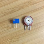
Parts are here. Problem on trimmers.
The trimmer legs fit perfect into the board. I don't have to move them. However, the trimmers aren't as tall as the original Piher trimmers, which are Amphenol Piher now. One trimmer is okay and I can reach the trimmer tool to adjust. But the P2 (DC offset) trimmer adjustment screw butts into the BJT transistor, and that's without the heat sink on it.
So now I find myself needing taller trimmers and wondering if I should just buy the Piher style, instead of the Bourns??
The trimmers in the pics are just loose fit, not soldered.
Attachments
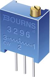
I think this may be the unit I need: Bourns 3386X 3/8" 500 ohm side adjust, stands about 10mm.
pin config: 321 3386X-1-501LF Bourns | Mouser
pin config: 123 3386H-1-501LF Bourns | Mouser
I assume that since the original Piher trimmers turned CW to increase value, that I need 123 pinout (3386H).
pin config: 321 3386X-1-501LF Bourns | Mouser
pin config: 123 3386H-1-501LF Bourns | Mouser
I assume that since the original Piher trimmers turned CW to increase value, that I need 123 pinout (3386H).
Last edited:
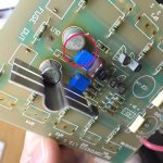
I don't know what I was thinking ... the trimpots are on the solder side of the boards ... but there is still the fuse/fuse holder to contend with. I can use the trimpots I have, but they are too small and require positioning at an angle in order to get the adjustment tool in. I'm going to order the larger trimpots. They'll be at least equal to the Piher single turn that were in there, if not better. I'm guessing better based off my experience with Bourns.
I don't know what I was thinking ... the trimpots are on the solder side of the boards ... but there is still the fuse/fuse holder to contend with. I can use the trimpots I have, but they are too small and require positioning at an angle in order to get the adjustment tool in. I'm going to order the larger trimpots. They'll be at least equal to the Piher single turn that were in there, if not better. I'm guessing better based off my experience with Bourns.
Why not eliminate the speaker protect fuse that is mounted on the board? You already have speaker protect fuses in the back panel of the amp so the board mounted fuses are redundant and not needed. Remove the fuse then desolder and remove the fuse clips and solder an 18ga wire across the old fuse location. Then you can use the trim pots you have.
"the board mounted fuses are redundant and not needed"
Read my last post again.
You have speaker protect fuses, two of them in series per channel (4 total), you only need ONE per channel (two total)! Eliminate the board mounted fuse and keep the one in the rear panel above the binding posts.
Irregardless of what you do with the pots you should eliminate one of these redundant fuses because they do hurt sound quality.
Okay. I remember someone on this thread mentioning that the speaker terminal fuses aren't all the effective.
If I remove the fuseholders, that the schematic shows to be 7.6 amp fast-blo ... does it make sense to put that value fuse at the speaker terminals?
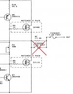
I modified a picture showing how your amp is set up. Eliminate one of those.
If the point of the speaker protect fuse is to protect your speakers then a 7.6A fast blow is just about zero protection. This fuse value shouldn't be spec'd as it should be set based on the speakers you are using. I provided a link to a hafler manual in an earlier post many many posts back in this thread that had some decent info about speaker protect fuse sizing. You may want to refer to that.
Attachments
Its not going to hurt anything so I'd leave the resistor in place.
The only reason I can think of that B&K included the resistor paralleled with the fuse is to ensure that the speaker out has no stored charge on it if the speaker protect fuse blows. If you want the same protection then add a resistor of approximately the same value across the rear panel mounted speaker fuse holder once you remove the board mounted fuse.
Just to be clear do not add a fuse across the AC mains fuse holder, only the speaker protect fuses.
Let me throw a fly in the ointment ...
I'm considering buying the Soft Start / Speaker Protection Kit from the diyAudio Store if after the recap, I decide I want to keep this amp long term.
Now with that in mind, would your suggestion change? In a way, I'd like to simply recap, with same values, and replace out of spec trimpots. But once I solder in the output boards, I'd prefer that any future changes don't require me to pull the boards again. Although, it should be easier now that the legs that were stuck to the pcb board itself, shouldn't do that again.
Your thoughts?
I have to run out to finish up other projects today, and won't get back to this until tomorrow. I do appreciate your continued help KC")
I'm considering buying the Soft Start / Speaker Protection Kit from the diyAudio Store if after the recap, I decide I want to keep this amp long term.
Now with that in mind, would your suggestion change? In a way, I'd like to simply recap, with same values, and replace out of spec trimpots. But once I solder in the output boards, I'd prefer that any future changes don't require me to pull the boards again. Although, it should be easier now that the legs that were stuck to the pcb board itself, shouldn't do that again.
Your thoughts?
I have to run out to finish up other projects today, and won't get back to this until tomorrow. I do appreciate your continued help KC
Let me throw a fly in the ointment ...
I'm considering buying the Soft Start / Speaker Protection Kit from the diyAudio Store if after the recap, I decide I want to keep this amp long term.
Now with that in mind, would your suggestion change? In a way, I'd like to simply recap, with same values, and replace out of spec trimpots. But once I solder in the output boards, I'd prefer that any future changes don't require me to pull the boards again. Although, it should be easier now that the legs that were stuck to the pcb board itself, shouldn't do that again.
Your thoughts?
Yes my suggestion would change, eliminate the speaker protect fuses completely once the protection boards are installed. With the DC protection pcb kit you do not need speaker protection fuses.
If this is what you plan to do in the future then bypassing the fuses on the output boards now while they're apart is the right thing to do. This is because all you'll have to do in the future is reroute the speaker wiring to bypass the rear panel mounted fuses once your protection circuit boards are installed.
I can't tell right now, but I assume that when I remove the fuse holders, it will be obvious which two solder points I connect with 18g wire?
I'm glad I mentioned this. If I like what I hear after this is done, I will most likely get that kit because it seems the right thing to do, whether I keep, or someone else gets to enjoy. The idea of making the amp safer to enjoy, just makes sense.
I'm not sure how much more I'm going to do for hobby stuff today. I wish I was retired. But I spent the afternoon in the local wood shop (DIY Cave) sanding down wood caps for some DCM TimeWindow 3 speakers I plan on running off this amp. And then I was able to sand down thick wood slabs for some speaker stands ... all to say that even if I can finish this amp today, I got through one phase of two other projects.
Enjoy the rest of your weekend KC, and I'll be back on in the next few days when I'm ready to tackle this. It is possible I may at least remove the fuse holder on one board so that I can post a pic for reference on connection points ... if needed.
I'm glad I mentioned this. If I like what I hear after this is done, I will most likely get that kit because it seems the right thing to do, whether I keep, or someone else gets to enjoy. The idea of making the amp safer to enjoy, just makes sense.
I'm not sure how much more I'm going to do for hobby stuff today. I wish I was retired.
But I spent the afternoon in the local wood shop (DIY Cave) sanding down wood caps for some DCM TimeWindow 3 speakers I plan on running off this amp. And then I was able to sand down thick wood slabs for some speaker stands ... all to say that even if I can finish this amp today, I got through one phase of two other projects.Enjoy the rest of your weekend KC, and I'll be back on in the next few days when I'm ready to tackle this. It is possible I may at least remove the fuse holder on one board so that I can post a pic for reference on connection points ... if needed.
- Status
- This old topic is closed. If you want to reopen this topic, contact a moderator using the "Report Post" button.
- Home
- Amplifiers
- Solid State
- B&K ST-202 Plus :: hum