Gotcha. I see the DC on the display corresponding with mA. Thanks!
So just to verify ... I'm okay with the meter probes across one fuse holder. Test one channel first. Power off, insert fuse ... remove fuse to test other channel. Report findings if good, or proceed to adjust P2 trimpots. I know where those are.
I assume that if I need to adjust, the channel with the highest bias should be done first. I also assume, like adjusting DC offset, I may need to repeat procedure, back and forth, until I get steady reading?
Again, thanks for being patient with me guys. I'm hoping this eliminates (most) of the hum.
-----
Crossed posts with Chamberman ... ok, so maybe I don't do this unless I can confirm my meter is good enough to read 100mV. Hmm.
Reading the manual for that meter, its VAC measurement is acurate for 50 / 60 Hz, not 20KHz. Probably the best you can do is get your tone generator (iphone, laptop, whatever) set to 100mV AC with a 60 Hz tone and then change it to 20KHz and see what your meter measures it at.
After the inrush, is your bulb dimmly lit while the amplifier is idling? What Watt bulb are you using?
After the inrush, is your bulb dimmly lit while the amplifier is idling? What Watt bulb are you using?
Reading the manual for that meter, its VAC measurement is acurate for 50 / 60 Hz, not 20KHz. Probably the best you can do is get your tone generator (iphone, laptop, whatever) set to 100mV AC with a 60 Hz tone and then change it to 20KHz and see what your meter measures it at.
There you go, set it for 100mV at 100Hz then set your tone generator for 1,000Hz and check the voltage then try 10kHz, if the 100mV reading is stable then increase it to 20kHz. If your using a piece of consumer gear you may see a drop-off at high freq. If there's a big drop in voltage at 20kHz try backing off to 19kHz and see if the volts come abruptly back up. The Denon USB DAC I had a couple of years ago had a roll-off at around 19kHz so I had to allow for this when I improvised it as a sine generator one time.
Realistically I'd probably just set the damn DC bias at idle with no input signal and call it good. That B&K procedure seems like a lot of work to set something that should be able to be specified at idle. A lot of manufacturers spec their DC bias settings at idle, with the amp warmed up for a period of time and no input signal. Now that you know how to use your meter to measure the DC mA across the fuse holders I'd try setting the amp for 200mA of bias and let the amp sit idle for an hour then recheck the bias current and the heatsink temps, they should be slightly warm. Make sure you put the cover back on between adjustments as this can have an impact on heat and bias.
You only want the heatsinks temps slightly warm at idle without a signal because as you found out yesterday they will heat up greatly once you begin putting a signal and heavy load on the amp. Also keep in mind that irregardless of what the manufacturer specs, if the heatsinks are getting hot enough that you cannot hold your hand on them for more than a few seconds when in normal use then you need to back off on the idle bias current because that's too hot and leaving the bias set that high and the output stage running at that high of a temperature can cause a failure.
Ok, a lot of great help here ... I really appreciate it guys!
I think my first step will be Chamberman's previous "quick" bias and see how that goes. If I still have any concern, I can try the elaborate method spec'd by B&K.
At this point, I'm more curious about how much bias I have, and if it's the cause of the hum.
I'll report back later today when I have a chance to hookup back up ...
RiLoWa ... I have 100w and 40w bulbs. For amps, I usually start with the 100w, since they are usually around 200 wpc amps.
you can weld a 10 ohm resistor on each positive rail fuse dc of the power supply and then measure the voltage drop to transfer this resitance and then deduce the current.
or weld a 10 ohm resistor on the bias adjustment potentiometer (between the base and the brush) and measure the voltage drop across this resistance
or, if you have an ampere meter, you remove a power supply fuse and then replace the fuse with the dots on your multimeter to Ampere dc
Oh, does polarity on the meter matter when measuring across the fuse holder? I can't see the board print side well enough to determine direction ... and the schematic I got here is too blurry to read +/-.
if you have an ampereter, do not worry about the polarity
if you have a voltmeter and resitance instead of the fuse, do not worry about the polarity
Hmm. So I just went for it and measured bias current across the fuse holder on one channel. Powered up with variac. Only reading was 0.01mV and only for short bursts ... at full power was at 0.0mV ... the only time I got a reading was on the left channel, with probe lead polarity swapped. It was blinking back and forth between 0.0mV and 15mV, then 17mV ... each time it bounced back from a zero reading the mV would increase by a few mV.
Again, the hum level through the variac is acceptable.
Again, the hum level through the variac is acceptable.
Meter was set to mA in DC mode. When I tried the 10A setting (yellow area on my meter) it was also in DC mode.
I have resistors and batteries galore. I should be able to follow your test instructions in a couple of hours. I have to meet a work deadline. I hate how that gets in the way.")
Thank you for helping!!
I have resistors and batteries galore. I should be able to follow your test instructions in a couple of hours. I have to meet a work deadline. I hate how that gets in the way.
Thank you for helping!!
Last edited:
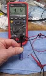
Try this quick test to see if your meter is measuring DC mA. I used a common value 100ohm resistor, the battery was new so if your battery is old then you may see less current. The main thing is whether it reads the current or not.
To get the picture I had to come up with a way to hold the whole thing with one hand so its a bit obscured but I think its self explanatory.
To get the picture I had to come up with a way to hold the whole thing with one hand so its a bit obscured but I think its self explanatory.
Attachments
- Status
- This old topic is closed. If you want to reopen this topic, contact a moderator using the "Report Post" button.
- Home
- Amplifiers
- Solid State
- B&K ST-202 Plus :: hum