Hello,
This is my first post, although I've been a member for awhile, and have been scouring the archives to try to figure this out on my own, but I am stumped.
I've built 22 tube guitar amps, 2 mono block audio amps, diagnosed and repaired several tube amps, and refurbished an Accuphase C200 and an Adcom GFA 5500, but I admit I am not trained or very skilled yet with solid state.
I picked up a 555 II for a great price that needed power supply caps and the electroytics replaced on the input board. I decided to install one of Chris Hoppe's power boards, as well as differential transistors that he matched for me. The amp sounded fantastic, ran great for 4 hours, then what turned out to be a damaged trace on the input board let go and the amp blew the negative rail fuses, so I completely disassembled the amp again, and tested all of the output transistors, drivers, everything, with guidance from Chris.
I repaired the trace, and also replaced the 2SA1210 with KSA1381ESTU, the 2SC2912 with KSC3503DSTU and the 2SC2240 with KSC1845FTA - all from Mouser, and not because they had failed, but because of the concern they may have been stressed when the trace failed and the neg. rail fuses let go.
I have had the input board in and out several times now, testing each component and re-checking all traces and solder joints, trying to figure out why the distortion alert indicators are glowing (not at all 1st 30 sec., then dim glow after) with no input signal. I've tried it with shorted and open inputs, no change. Using 8 Ohm dummy loads, the amp biases fine (replaced bias pots with multi-turn sealed). DC offset is 0.2ma left channel, .8ma right channel.
I have a digital oscilloscope, but my function generator was kaput, and has just now been replaced.
Can anyone give me some guidance on this, please? This was intended as a learning project to help me improve my solid state skills, but now it's just tormenting me, because I was so impressed with how well it performed and sounded before it crapped out, and I've spent good $$ and time getting this far. Thanks very much for any assistance,
Greg
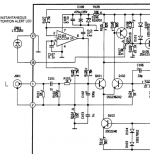
The input differential pair runs at about 2 mA total current. It should split 1 mA each side (Q101, Q102). If the audio input get so high that on the peaks all the current ends up in Q102, then there will be enough voltage across R106 to turn on Q104. Turning on Q104 turns on the LED.
Under idle conditions, you should see about 0.4 volts across R106 and about 8 volts across R105. Same should be true for the equivalent components on the other channel. Measure the voltage across R114 and we can calculate those drops more precisely.
This is occurring on both channels? As the overload LED comes on, do both channels come on at about the same rate?
Attachments
Looks like there is a bit of imbalance between the currents in the input pair. The input side is drawing 1.33 mA, and the feedback side is drawing 1.47 mA. That imbalance is pushing the distortion sense circuit to detect early. The total emitter current is 2.85 mA, and that should split evenly between the two transistors in the differential pair. Ideally, that would give you and idling voltage across R105/R155 of 1.18 volts and across R106/R156 of 0.52 volts.
What are the DC offsets at the outputs of the amp?
What are the DC offsets at the outputs of the amp?
Hmm, can't argue with those. Really don't know where else to go. The DC impedances feeding either side of the diff pair are quite different, so that could account for the current imbalance. I've seen some postings elsewhere indicating the Adcom 3A's can be problematic. But your offsets are good.
If all you want to do is to reduce the sensitivity of the distortion detection, you could reduce the value of R106/R156 - perhaps try 301 ohms. That will not have any effect on anything other than overload detection.
If all you want to do is to reduce the sensitivity of the distortion detection, you could reduce the value of R106/R156 - perhaps try 301 ohms. That will not have any effect on anything other than overload detection.
Hmm. I previously replaced the 3As with AD820s, thinking they might be part of the problem. Maybe I'll reinstall the 3As.
I had wondered if subbing the KSC1845 for the Q103/153 2SC2240 had caused an imbalance, but didn't put back the originals because the hFE was quite low on one. At this point, I have even replaced the original 2SA1016, thinking the KSA992 were a problem - no change, though the hFE were quite high with the first batch I bought.
In your first post, you indicated R105/155 should measure about 8V across each; is my 1.10V at all tied to Q103?
Thank you - I really appreciate you trying to help figure this out. You have been helpful with pointing me in the right directions to diagnose.
Hi Greg,
Q103 cannot cause an imbalance. The two emitters are connected directly together to Q103's collector. However, the amp is sensitive to the match for Q101 and Q102. If you can find my transistor matching jig (Adcom 565 thread I think), you should use that to get tight matches. You can't really use a meter hFE test as the transistors must be at identical temperatures for the numbers to be useful. If you're careful you can use a meter hFE tester to pre-sort the transistors.
R105 is across the base-emitter junction of Q107, plus 2 * Vbe for the distortion lights to come on. Your normal voltage should run about 0.75V as a rough guess (given 1.83mA tail current for 0.91mA through each side * 825R). So it does sound like you have some kind of imbalance in the circuit.
Just for giggles, check R104 (100R) for being burned open. That can cause funny problems. If you measure from one RCA ground to the other, you should measure about 200R without anything else plugged into the amp.
What does the output of IC101 measure? Please put the original one back in as well.
-Chris
Spent some time putting models for the KSC1845 and the 2SC2240 into LTSpice. If the models I used are accurate, for the given circuit, the KSC1845 will provide a little bit more current to the diff pair than the 2SC2240. (In the sim, the KSC1845 give me 2.85 mA, and the 2SC2240 gives me 2.71 mA) Not much difference, but the difference is in the direction to make the distortion detector more sensitive. If you want to drop the current back to 2.71 mA using the KSC1845, you can change the 301 ohm resistor to 324. ...But we are really starting to nit-pick here.
My typo.. Should have been 0.8 volts. I had guessed the current was a bit less than it actually is.In your first post, you indicated R105/155 should measure about 8V across each; is my 1.10V at all tied to Q103?
Last edited:
Hi Chris,
Thank you very much for your reply.
Q101/102 and Q151/152 KSC1845 were matched to within 1ma and supplied to me by Chris Hoppe, using the same type jig you are referring to.
I checked all 100R resistors (had to replace the fusibles when I first got the amp, but couldn't find fusibles in this rating/resistance, so used 1/4W flameproof), and they are good.
Measured the AD820s:
IC101: 7 to 4 = 19.578V, 6 to gnd = 4.52V
IC151: 7 to 4 = 19.536V, 6 to gnd = 4.47V
Replaced with original Adcom 3A:
IC101: 19.588V, 4.45V
IC151: 19.555V, 4.38V
Thank you for the help!
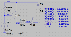
Did a quick sim of the distortion detector circuit using the quiescent values of I(Q102 collector) we determined earlier - 1.47 mA. That gives 0.536 volts across R106 which agrees with what you measured.
Under those conditions (no input signal), the LED is getting about 0.82 mA of current - depending on the LED probably enough to see it lit.
IC101/151 are sitting there open loop for DC. There is really no way of adjusting the balance of the input pair, the feedback is going to push it to where it is no matter what you do. I suppose if you wanted to play, you could force an offset into IC101/151.
I'm going to go back to something I suggested earlier, and that is to reduce the value of R106/156 to 301 ohms. That reduces the quiescent LED current from 0.82 mA to 23 uA.
Attachments
Hi Ylli,
Thank you again for your time and effort on this. I'll order some 301R and swap those.
One thing I haven't done is put an audio signal through the amp and actually listened, despite the distortion indicators. I don't have a distortion analyzer, but at least that might be a sniff test...
Cheers
Thank you again for your time and effort on this. I'll order some 301R and swap those.
One thing I haven't done is put an audio signal through the amp and actually listened, despite the distortion indicators. I don't have a distortion analyzer, but at least that might be a sniff test...
Cheers
I tend to side with anatech here, look for the reasons why it does what it does first.
I suspect if you refit the original fitment devices for Q103 and Q104 then it may well be back to normal. Different manufacturing processes give slightly different forward turn on voltages (Vbe) and this arrangement looks pretty critical on that.
Also the differential pair doesn't have to be balanced (as in seeing the same collector currents) and may well not be by deliberate design. The DC servo forces a low output offset voltage come what may.
Thank you, Anatech and Mooly. I appreciate your positions. I'll refit Q103 and Q104 and check operation, and report back. My original instinct was to refit all original transistors, but since it had been working perfectly with the replacements before the bad trace let go, I've been confounded.
Actually, I too agree with Anatech and Mooly. But I figured you had already changed enough parts (subtle differences from original) from the original that changing one more was not unreasonable. If you can replace all the changed parts with the originals, and that solves your problem, that *is* the best solution. If not, my suggested change will not affect anything except the sensitivity of the distortion detect.
Do let us know which direction you go and how things work out.
Do let us know which direction you go and how things work out.
... it had been working perfectly with the replacements before the bad trace let go,
You never did expand on that. What trace 'let go' and what did you do to fix that? What are the rail voltages and are they balanced?
- Status
- This old topic is closed. If you want to reopen this topic, contact a moderator using the "Report Post" button.
- Home
- Amplifiers
- Solid State
- Adcom GFA 555 II - distortion indicators with no input signal