No disrespect, but how is this different than just changing R106 to 301 ohms as I suggested quite a bit back? The only difference is that just changing to 301 ohms would increase the collector voltage on the feedback side by 0.083 volts. The two collector voltages are already quite a bit different by design.
None taken
")
I came to the thread after you posted that, and if I'm totally honest that post hadn't even registered consciously when I suggested splitting R106. That's all there is to it.
Anatech's suggestion of a parallel could work OK as well.
If you measure the collector volts of Q104 you could then calculate a suitable resistor to reduce the voltage across the LED to below its forward voltage rating. It might be a lower value resistor than you first think though.
As little as 2 volts at the collector could allow 100uA or more to flow in the LED, and with a high brightness part that would be very visible. Something as low as 10k could be needed in my 40 volt supply example earlier.
Another off the wall idea would to add a series Zener to the LED. The Zener would need to be of higher voltage than the static collector voltage of Q104 and it would also have to be low leakage.
Very good point, Chris.
Other than the LEDs I replaced, I selected the same replacement parts that have been discussed and used by those here on this forum and elsewhere for this amp.
I have found that the original 2SC2240 part has a much lower hFE than the KSC1845 recommended as a replacement, and the original 2SC2912 has an hFE that is more than double that of the common replacement KSC3503DSTU.
I don't really understand how these replacement parts have worked for others without causing problems.
Based on the circuit imbalance identified by everyone here and the progressive improvement by rolling back my replacements to original, the LED selection isn't the main problem.
Recommended LEDs show up today, so I'll know more later.
Thanks everyone!
Well, transistor characteristics can vay 3:1 or more. Japanese transistors are graded at the factory, usually in three beta ranges. Within those ranges there is still huge variations between parts.
Good design work will create a circuit where transistor beta isn't going to cause trouble - within reason of course. That's really good news because beta varies a lot with temperature. Even the heat from your finger will change the beta
-Chris
Good design work will create a circuit where transistor beta isn't going to cause trouble - within reason of course. That's really good news because beta varies a lot with temperature. Even the heat from your finger will change the beta
-Chris
I understand what you're saying, Chris, but wouldn't everyone have similar problems with these substitute transistors in this amp?
I bought 10-20 of each part and sorted them - they all fell within a fairly tight range, and were consistently different than the original parts in this amp.
I bought 10-20 of each part and sorted them - they all fell within a fairly tight range, and were consistently different than the original parts in this amp.
I don't think your transistor substitutes were the problem, but in troubleshooting, you want to return the circuit to operating condition and start troubleshooting from there. When I develop a modification, I do it in steps. Tedious, but it's the only way to identify a change that doesn't work. You could look for the problem for days otherwise,
-Chris
-Chris
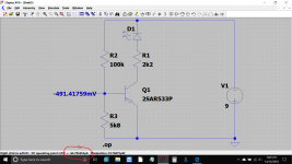
It might be fun to rig your old vs new transistors up in a little test rig like this and see at what B-E voltage they begin to conduct.
R3 in this diagram would be a 10k preset. For NPN transistors just flip the battery and diode. Even in spice world there is a big variation at the transition point between just beginning conducting and fully cut off for different devices.
This has nearly 100uA flowing in the LED and R1. Just 20 or 30 millivolt's difference in Vbe at this critical point can mean the difference between conducting a little or virtually off.
Attachments
Who said 'new LED's'? That could definitely be a factor.....
...I began to think about the downstream component that I had changed that could affect the current draw - the indicator LEDs. When I got the amp, one of the originals had broken pins, so I replaced all LEDs. ...
I remember in the 1970s, many LEDs leaked so bad they would not light at 1mA. Also they were barely bright at 20mA.
Both ends of operation have changed, "improved", since then. 20mA can be blinding. 1mA works fine and may be apparent indoors. If the design depends on LEDs which go-dark at low current, you may need old LEDs or a bleeder resistor, ~~2K.
Hi PRR,
Exactly!
Hi Mooly,
Often times vBE doesn't matter that much as the junction is operated on by current and the voltage drop is just a byproduct of that. The only time you might have something like that being important is when you are developing a voltage across a resistor in parallel with the base-emitter junction. Not too often in other words. The other case would be when several transistors are in parallel as current sinks. VBE can then make a difference in the current in each leg that is supposed to be equal, or a ratio of. VBE is also sensitive to temperature, so not something good to design to.
-Chris
Hello All,
The amp functions and sounds great now. It's been running for hours at a time, and has been cycled a dozen times with no issues.
I'm on a few tube amp forums, and as is the case here, there are usually a great bunch of folks willing to help out, and a small core of contributors with a valuable breadth and depth of knowledge, and the graciousness to help. I have learned a lot so far from your input, and have been motivated to get more serious about increasing my knowledge with solid state gear.
Thank you all very much!
Cheers,
Greg
Now you've found out about the differences between old and new style LEDs. I think many of us have to be reminded that even the most simple component deserves to be considered.
Yes, Chris - as well as differences with commonly accepted substitute transistors, subtle differences with diode characteristics, etc. Most important is getting help to think about the entire circuit interaction.
Thank you all,
Greg
- Status
- This old topic is closed. If you want to reopen this topic, contact a moderator using the "Report Post" button.
- Home
- Amplifiers
- Solid State
- Adcom GFA 555 II - distortion indicators with no input signal