Look at the ripple across C211 with R204 lifted. Should be very small.I do have a scope!
Look at the ripple across C211 with R204 lifted. Should be very small.
I'll start with the voltage, the scope is pretty crap and very slow.
Would i ground the lead to the chassis for the scope?
Would i ground the lead to the chassis for the scope?
Yes.
Would i ground the lead to the chassis for the scope?
ALWAYS ground the scope probe's ground lead.
NEVER connect the probe's ground lead anywhere else.
Otherwise can cause bad failure of both the DUT and the scope.
Floating (ungrounded) measurements require specialized, expensive equipment.
Last edited:
ALWAYS ground the scope probe's ground lead.
NEVER connect the probe's ground lead anywhere else.
Floating measurements require specialized, expensive equipment.
No - i understand that, it's just that the chassis isn't directly connected to the 0v 'star ground' on the schematic, it has its potential set by a 10nf cap. As a result I wasn't sure we'd get an accurate/useful reading.
Crazy thought (and I know, to many cooks and all that so I'll keep quiet) but is this overheating cap fitted correctly? Don't go off the board markings (which can be wrong on occasion) but go off the actual print layout.
IMPORTANT: Guys, I'm so, so sorry. I've realised that C211 actually is reversed in its polarity. As you quite astutely pointed out Mooly, the board is marked incorrectly compared to the schematic, it's also weird cause the c211 breaks a symmetrical pattern in the polarity of the 4 cap grouping of c210, c211, c212, c213. I think what happened was in my quest to discover why R202 had blown, I removed the original cap in c211 and tested it, then put it back in reverse due to the board markings. Even though i already told you it was DEFINITELY the right way round
. A fool I am... a fool. This means we've probably solved one problem. Since i replaced the Q201-Q204s while this cap was in reverse polarity, that might well have fixed the other problem too, we shall see.I'm gonna flip it round (i will order in more to replace it soon) and start over with measurements - will report back here tomorrow most likely.
I've thrown the first part of the circuit into a simulator and so this shows what you should see. Note the shift in DC levels as the circuit progresses (so you want the scope on DC coupling).
Attachments
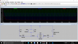

I've thrown the first part of the circuit into a simulator .
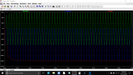
So did I:Attachments
Progress!
Mooly, Ylli and everyone else who has lent me advice so far - thank you all very much.
We have some progress... Now that C211 is correctly polarised, we have...
+60v at +VL/+VR
-60v at -VL/-VR
-65v at -67v (tp at far left)
+105v at +67v
So, still way too much power on the +67v rail. I already replaced Q201-204, so i don't think it is any of those - anyone got any ideas?
 thats a fix.
Yep - That did it!!!!! YOU LEGENDS - ALL OF YOU!
R217 on the negative rail was a bit out of spec too so i replaced that as well, I have lovely 60v and 67 v rails now, and no exploding capacitors.
Now i need to assemble and test the amp to make sure there aren't any more problems
R217 on the negative rail was a bit out of spec too so i replaced that as well, I have lovely 60v and 67 v rails now, and no exploding capacitors.
Now i need to assemble and test the amp to make sure there aren't any more problems
Its strange how the resistors NAD deliberately specify as MF (metal film) are the ones that fail.
It might be worth both of you replacing both 22k's in the power supply and also if this amp is similar to the NAD 216, replace both 160k's in the main amp on both channels.
Resistors do actually have a voltage spec as well as the usual power dissipation but normally this is in the 150 volt and higher region.
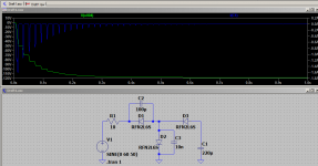
Stage 2
Yes - I mentioned I replaced the other 22k which is r217 on the negative rail, it was also out of spec, though only slightly high! Thanks for this, I will check out the 160Ks.
Thanks
I'm pretty lost on that one too :S
-------------------------------------------------------
Okay people, we have a perfect power supply now, stable 60v+/- and stable 67v +/-. The amp had two problems, which I had hoped were being caused by the power supply as i was unable to find any issues in the tone board or input board.
Problem 1 - when switched on the amp emitted a very loud buzz for about 10 seconds.
This has been completely fixed by addressing the issues in the power supply.
Problem 2 - when first turned on, one hears music loud and clear, which instantly starts to fade out and become sort of bit-crushed. Within 10-15seconds, it has faded out completely. Restarting the amp repeats this symptoms. The problem happens in BOTH channels, and happens on headphones too
This problem remains.
This amp has a pre-amp out and a power amp in on the back of it, connected with jumpers. I can confirm that the power amp works perfectly in isolation. The weird fadeout/bit-crush thing is happening in the preamp for sure.
Looking to page 14 of the schematic, the 'input & volume pot' page - I can confirm that the +/-67v rails which input at D657 and D658 are present, and being correctly rectified to 24v+/- rails at those test points. IC651 appears to be working well.
I can confirm that correct voltages are all present at J505.
Anyone got any ideas? There were a couple of swollen caps in the tone control board (page 15), which i replaced. I also replaced the IC761A headphone amp. I haven't spotted anything else out of the ordinary there.
Its strange how the resistors NAD deliberately specify as MF (metal film) are the ones that fail.
It might be worth both of you replacing both 22k's in the power supply and also if this amp is similar to the NAD 216, replace both 160k's in the main amp on both channels.
Yes - I mentioned I replaced the other 22k which is r217 on the negative rail, it was also out of spec, though only slightly high! Thanks for this, I will check out the 160Ks.
Them dam resistors Huh Mooly
Thanks
I'm still scratching my head why the reversely polarized cap C211 could have affected the low impedance -60V rails ...
Best regards!
I'm pretty lost on that one too :S
-------------------------------------------------------
Okay people, we have a perfect power supply now, stable 60v+/- and stable 67v +/-. The amp had two problems, which I had hoped were being caused by the power supply as i was unable to find any issues in the tone board or input board.
Problem 1 - when switched on the amp emitted a very loud buzz for about 10 seconds.
This has been completely fixed by addressing the issues in the power supply.
Problem 2 - when first turned on, one hears music loud and clear, which instantly starts to fade out and become sort of bit-crushed. Within 10-15seconds, it has faded out completely. Restarting the amp repeats this symptoms. The problem happens in BOTH channels, and happens on headphones too
This problem remains.
This amp has a pre-amp out and a power amp in on the back of it, connected with jumpers. I can confirm that the power amp works perfectly in isolation. The weird fadeout/bit-crush thing is happening in the preamp for sure.
Looking to page 14 of the schematic, the 'input & volume pot' page - I can confirm that the +/-67v rails which input at D657 and D658 are present, and being correctly rectified to 24v+/- rails at those test points. IC651 appears to be working well.
I can confirm that correct voltages are all present at J505.
Anyone got any ideas? There were a couple of swollen caps in the tone control board (page 15), which i replaced. I also replaced the IC761A headphone amp. I haven't spotted anything else out of the ordinary there.
Last edited by a moderator:
- Status
- This old topic is closed. If you want to reopen this topic, contact a moderator using the "Report Post" button.
- Home
- Amplifiers
- Solid State
- NAD 319 Repair