Latest Measurements
Good Morning
Thanks a lot for all your inputs and your efforts to help me.
Here are some answers to your questions, please refer to the pictures.
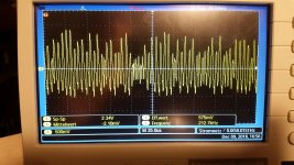
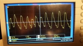
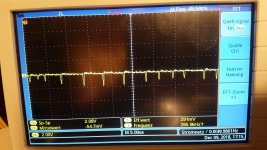
The noise is obviously some high frequency oscillation. On the first two pictures you see the noise on the 30V rail on the 25us and 5us scale.
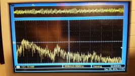
In the 3rd picture you find an FFT of that.
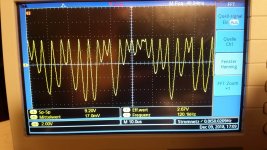
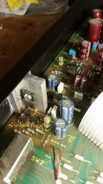
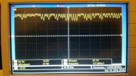
In the fourth picture you see the heavy noise, obviously also an oscillation that appears on the collector of Q602 and Q601 in the power supply.
In the last picture you see the spikes on C601 (the 10000uF cap) on a high resolution timescale.
Unforturnately I won't have hardly time today for further investigations.
Christian
Good Morning
Thanks a lot for all your inputs and your efforts to help me.
Here are some answers to your questions, please refer to the pictures.
The noise is obviously some high frequency oscillation. On the first two pictures you see the noise on the 30V rail on the 25us and 5us scale.
In the 3rd picture you find an FFT of that.
In the fourth picture you see the heavy noise, obviously also an oscillation that appears on the collector of Q602 and Q601 in the power supply.
In the last picture you see the spikes on C601 (the 10000uF cap) on a high resolution timescale.
Unforturnately I won't have hardly time today for further investigations.
Christian
Attachments
So we need to concentrate on the 30 volt line.
As we have had doubts on the measurement set-up I would suggest very quickly tagging a series resistor and cap across the 30 volt rail and then remeasure the noise across the cap just added.
Try what you have but something like 1k to 10k and 100uF to 1000uF should pretty much kill any noise and give you a straight line trace.
I would do that first and then we know that what you are seeing is real... which it looks more likely it could well be.
If that is OK then look at the reference for the 30 volt rail which is Zener D603 and the cap across it. That voltage has to be super clean. Is it?
So we need to concentrate on the 30 volt line.
As we have had doubts on the measurement set-up I would suggest very quickly tagging a series resistor and cap across the 30 volt rail and then remeasure the noise across the cap just added.
Absolutely noise free after the low pass. And its noise free after the zener.
So I am going to recap that power supply as a next step.
As Mooly says its an odd ball fault . I thought photo 4 above looked like current starvation oscillation . Are you actually getting +30V and +10V out of the power supply ?
Yes, +30V plus the oscillation showed in one of the previous posts, and yes +10V, much cleaner than the +30V.
Observation ...ref photo 4 .... a 9.2V variation at the collectors of Q601 and Q602 means a variation of 9.2V across R604 (1K0) which equates to a variation of 9.2mA virtually the whole current available delivered by the current source which suggests Q602 is switching on and off.
The question is, what could cause the regulator to oscillate this heavily? Dead C604? (Note: Use a 50 V or higher part.) There still is a 100n in parallel which should normally make oscillation at such a high frequency hard, but you never know. Bad solder joints on any of Q601..604, or one of the transistors themselves being degraded from decades of running hot (Q604 probably being the most likely candidate)?
The question is, what could cause the regulator to oscillate this heavily? Dead C604? (Note: Use a 50 V or higher part.) There still is a 100n in parallel which should normally make oscillation at such a high frequency hard, but you never know. Bad solder joints on any of Q601..604, or one of the transistors themselves being degraded from decades of running hot (Q604 probably being the most likely candidate)?
These are my thoughts too. Therefore I ordered all these parts. I will get them on Thursday and find time to work on the amp next Saturday. I keep you informed...
The two 2SA.... transistors are running very hot, perhaps these have degraded
solder joints ok, already everything resoldered
Yeah, two 2SAs? There's only one pnp in the 30 V regulator, that's Q601, a BC556B on my schematic. That should be running at ~130 mW, which is a decent but in no way unmanageable amount of dissipation for a TO-92. The other hot-running pnp I would guess to be Q608 (2SA1488), but that's in the 10 V regulator. Q603 is listed as a BC546B, Q604 a 2SC3851.
So is this a different revision board using different types or did someone substitute Q601 at some point without playing the game of "Twist and Shout"? (I don't think this would even work, but...) BC556B is EBC pinout, Japan types are usually ECB. If the board is supposed to take an EBC, the middle pin of Q601 would go to D602 / R601, for an ECB it would go to R604.
So is this a different revision board using different types or did someone substitute Q601 at some point without playing the game of "Twist and Shout"? (I don't think this would even work, but...) BC556B is EBC pinout, Japan types are usually ECB. If the board is supposed to take an EBC, the middle pin of Q601 would go to D602 / R601, for an ECB it would go to R604.
Last edited:
sorry guys
it is one 2SA1488 and one 2SC3851 which are mounted on a cooler and they run pretty hot. Perhaps they just aged.
As I said, I am waiting for parts now....
On the picture the situation and once again the collector of Q602. You can see that it sits on 30V with these high frequency voltage drops of more than 9V
Attachments
") OK, mystery solved.
OK, mystery solved.Some Japanese transistors that run hot can fail in peculiar ways, something I've encountered many times over the years in TV's and the like.
I would think something like a TIP41C would replace that 2SC on the heatsink. In fact all those could be substituted with common BC/2N devices as long as you observe the pinouts.
It will be interesting to see just what this turns out to be.
I have been working out the loads on the +30V and +10V rails
+10V .... 2x93mA = 186mA...... so power over Q608 = 20x0.186 = 3.72W
+30V .... 2x17mA = 34mA +186mA (+10V rail) +9.5mA (various) =229.5mA....so power over Q604 = 14x0.2295 = 3.21W
A way for the collector of Q602 to be going to +30V is if very little current is flowing through R604 (1K0) at that moment so the approx. 7mA current from the current source must be flowing elsewhere ......... What if the collector of Q603 is open circuit.............. then the +30V series regulator would be reliant on the hfe of Q604 alone . Now 229/7mA = 33 which is getting close to a possible hfe for Q604 and so the current source could be limiting the output of Q604 and causing the oscillation
PS the collector of Q602 should normally be sitting around +23V .
Last edited:
- Status
- This old topic is closed. If you want to reopen this topic, contact a moderator using the "Report Post" button.
- Home
- Amplifiers
- Solid State
- Audiolab 8000a Background noise/hiss