Hi, I am trying to get a Sony STR-6800 SD receiver to work. Symptoms are:
It seems that the FM module influences the working of the protection relay (AM works fine). I noticed that the power supply winding used by meter lighting and Dolby circuit is shared with the mains switch off detection of the protection relay network (T11). My initial guess was therefore a power supply issue in this circuit, but I can't find any obvious clues. The schematic does not say what the AC voltage should be. I would not be surprised if some caps have died, but which ones to check?
Who can provide a diagnosis? Thanks, Jan
- Sometimes switching to FM engages the protection relay (sound is interrupted), switching to another source resets the relay
- Sometimes invoking the muting button on the tuner part (i.e. muting on) engages the protection relay
- Without the muting button on, there is no stereo sound and the stereo light is off, engaging the muting button gives stereo sound with stereo light (if it does not invoke the protection relay)
- Sometimes invoking the muting button results in distorted sound, switching muting off returns to distortion free mono sound
- Most often, invoking the Dolby switch engages the protection relay, though there are times that it works and the Dolby light comes on
It seems that the FM module influences the working of the protection relay (AM works fine). I noticed that the power supply winding used by meter lighting and Dolby circuit is shared with the mains switch off detection of the protection relay network (T11). My initial guess was therefore a power supply issue in this circuit, but I can't find any obvious clues. The schematic does not say what the AC voltage should be. I would not be surprised if some caps have died, but which ones to check?
Who can provide a diagnosis? Thanks, Jan
I suggest you monitor the +15V used in the tuner, maybe at R263 or R416. Inspect / reflow Q212 solder joints and, if nothing found, monitor voltage on emitter and then collector. If input +30V is anything but stable, follow it back to C917 and R913 (value / solder joints). Otherwise suspect degraded Q212.
invoking Dolby in AM mode also invokes protection relay.
I would go with the presumption that the protection circuit itself has a problem.
Check/replace the electrolytic capacitors and resistors in it, especially the power resistors.
Thanks for your help. But that would not explain the signal distortion by the muting circuit (#4 above), nor would it explain why stereo sound is only available with muting on (#3, unless that is per design?).
I am replacing caps in the power section to the tuner part and the larger resistors that tend to fry the PCB: R911, R912, R194, C911, C912, C917 on the power amp board and all voltage stabilizing caps on the tuner board, like all 100u/16V like C201, C218, C317, C318 C245, C416 and the caps around Q212. This of course assuming it is a power supply issue in the FM circuit.
I am replacing caps in the power section to the tuner part and the larger resistors that tend to fry the PCB: R911, R912, R194, C911, C912, C917 on the power amp board and all voltage stabilizing caps on the tuner board, like all 100u/16V like C201, C218, C317, C318 C245, C416 and the caps around Q212. This of course assuming it is a power supply issue in the FM circuit.
And voltages remain stable even when the unit acts up? So much for that theory then.Ok, here's an update: voltage upstream of Q212 is 30V during all tests. Voltage at R263-R416 is 15.47 with FM on during all tests and 15.56V when FM is off. So Q212 is doing what it should.
At this point I have to wonder whether the problem isn't actually mechanical in nature and triggering a crack or bad solder joint, most probably on the tone control PCB. Can you provoke the problem with the multipath switch as well?Ad 5) above: invoking Dolby in AM mode also invokes protection relay.
No, only with Dolby. It's funny, sometimes I cannot use FM at all, sometimes I can tune with muting and Dolby on. There is no consistency. Do not forget the distortion (sometimes, but quite frequent) with muting on. That does not suggest a cracked / bad connection to me.
How is the relay triggered, is it via the start-up delay which is linked to the FM section via T11 (to the lamp and led driver and the Dolby section via S14), or is it via the power amp output (protection)? My guess it's the start-up delay.
How is the relay triggered, is it via the start-up delay which is linked to the FM section via T11 (to the lamp and led driver and the Dolby section via S14), or is it via the power amp output (protection)? My guess it's the start-up delay.
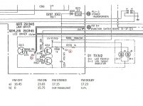
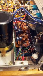
I took some measurements around the lamp / led driver as this is connected to the relay via T11, see attachment. Point a) target value should be 13V. I find different values depending on if FM is on or not.
Not sure where the high voltage of 23V is coming from.When the stereo light comes on it drops almost 6V.
The AC voltage of the transformer winding to this circuit (and the lamps) is about 11V.
Not sure where the high voltage of 23V is coming from.When the stereo light comes on it drops almost 6V.
The AC voltage of the transformer winding to this circuit (and the lamps) is about 11V.
Attachments
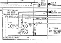
Where was your ground reference for this measurement? I would try comparing the voltage directly across C254. You may be dealing with a bad ground connection there. Those can cause some really funky problems, BTDT. Where is that even coming from on this board? They clearly forgot to draw the symbol for one thing (see 5800SD schematic). Maybe it's coming in via a mounting screw or something? That would be a classic. Loosen & tighten back up.
Last edited:
Reference: I measured between the chassis and R268-R270. If I measure directly over C254 (at the emitter of Q215) I measure 13.5V with FM on and off. So my earlier post was wrong, this does not point to an error and so I still have no clue why switching to FM invokes the protection relay.
Not so fast. Where did you have your ground connected earlier? If it was supposed to be an actual ground point, the bad connection has to be somewhere between there and C254. The multimeter should verify this, either by voltage drop (there shouldn't be very much at all) or resistance measurement (when powered off).
I had plenty of fun chasing down bad ground connections in a fancy Onkyo tuner once. The unit would sporadically glitch out and go into an inoperable state. Ground was distributed on the board using some copper bus bars or whatever you call these things, and some solder joints on those turned out to be faulty.
I had plenty of fun chasing down bad ground connections in a fancy Onkyo tuner once. The unit would sporadically glitch out and go into an inoperable state. Ground was distributed on the board using some copper bus bars or whatever you call these things, and some solder joints on those turned out to be faulty.
(-) at C254 is only "floating" because they forgot to draw the ground symbol on the schematic - errare humanum est. The circuit does not make any sense (and would not work) otherwise, and if you consult the 5800SD schematic, you will find the same kind of circuit drawn correctly.

Attachments
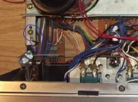
I was looking at the STR-5800 schematic. I noticed the units are almost identical. Didn't know that. I have ordered an original service manual of the 6800 because the free versions on the web are incomplete and of so-so quality. The 5800 version is much nicer. Anyway, I looked at some photo's of the inner 5800 and noticed a ground that I have not seen on my machine. Turns out the 6800 has it too. But mine has not! Someone must have removed it or forgot to put it back? There was some minor work done on my machine: dial bulbs were replaced with leds and R911/912 were replaced. So where does this black wire go?
Attachments
On the 5800SD wiring diagram I can see only two explicit connections from circuit ground to chassis. One is at the phono input, the other comes from the power supply board. Given the general area, it might be the latter. Can you see the power supply board, output side? There should be a bunch of black wires fanning out from the area (all the power ground returns).
I suppose you could try measuring from power supply ground to chassis and input ground to chassis to confirm that this is the problem. Otherwise the problem could still be in one of the ground returns.
I suppose you could try measuring from power supply ground to chassis and input ground to chassis to confirm that this is the problem. Otherwise the problem could still be in one of the ground returns.
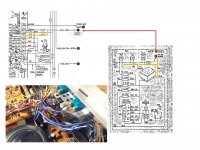
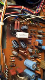
I think there should be a ground connection at the display lights as per the schematic (red circle). This would result in pin 4 on the FM board to be grounded via wire <402>. In my Sony there is no connection of wire <402> to the ground. I measure >100 K Ohm.
As you can see in the photo someone has added a small bridge rectifier and an electrolytic cap to feed the dial leds. When doing so, I think the AC wire leads (both blue, one thicker <402> one thinner <401> after the fuse) where switched, because the blue-white wire to pin 2 of the FM board should be fused, but now pin 4 is. I think I can switch these two back without any risk of damage. What do you think?
Furthermore my guess is that the person forgot to put the ground wire back connecting wire <402> with the chassis. So I am inclined to add a black wire between the chassis and the terminal of the meter bulb that connects to wire <402>. This should restore the missing ground. There should be no risk in doing this I assume. What do you think?
Attachments
Sony STR-6800 SD - solved
So I have rewired the power supply to the light bulbs which also includes the power off sensing wire to the protection relay and the power to the lamp / led drivers. Main problem here was that the wrong AC feed without the fuse was used.
Second I have restored the ground connection of the other AC wire to the chassis.
Now the machine works in FM mode without setting off the protection relay. Also when tuned to a stereo station the stereo light comes on. No need to muting to be on. The muting switch works as it should, no distortion anymore.
The only thing that is still odd is that the power supply to the Dolby circuit at R309 / R364 should be disconnected when Dolby is on via switch S14-1, but on my machine this switch is bypassed, so there is always a positive voltage at R309/R364. I do not know if this is from factory or not.
Overall conclusion: the person that has replaced the display / dial bulbs (PL2/PL3) with leds has really messed up the wiring and failed to restore the ground connection.
Hoping all is fine now, many thanks to sgrossklass for pointing me in the right direction!
If it keeps working I may decide to replace the remaining caps in the power and power amp sections.
Pictures: restored ground connection and replacement of cooked R's, C's and D's in the counter current prevention circuit.
Attachments
And now you know why techs tend to be wary of "pre-messed-up" units.
Congrats on the fix.
As for S14-1, maybe there were some contact issues with it and this was the easiest way to circumvent the problem. (Or maybe someone tried to troubleshoot the very same issues you had...) If in doubt, unsolder the bypass and measure contact resistance.
I'm still wondering why the SNR spec only says 90 dB, line level... does it have appreciable hiss or hum? Nobody seems to be complaining about any of that though, so it may just be a very conservative rating - it was the mid-'70s after all.
- Status
- This old topic is closed. If you want to reopen this topic, contact a moderator using the "Report Post" button.
- Home
- Amplifiers
- Solid State
- SONY STR-6800 SD erratic behaviour