Hello friends. Long time ago, I bought a pair of mosfet transistors with code IRFP150N to build a class A amplifier however I would like to build a class AB circuit with them. The amplifier should be "cuasi-complementary" because I have only two N-channel transistors and I would like to make use of them. Any suggestion to my requirement, I will thank you.
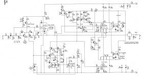
You could use them instead of the BUZ10's in my non-switching class-AB design from Electronics World February 1996. You won't have to worry about quiescent current stability then, because it controls that automatically.
If you are lucky it will work without any changes, if you are not you will have to change the frequency compensation a bit. The CA3046 is out of production, but it can be replaced with an LM3046.
If you are lucky it will work without any changes, if you are not you will have to change the frequency compensation a bit. The CA3046 is out of production, but it can be replaced with an LM3046.
Attachments
This amp looks very interesting.
Marcel, do you have a link to a pdf or something - with more info how it works?
Thanks,
Minek
Marcel, do you have a link to a pdf or something - with more info how it works?
Thanks,
Minek
You could use them instead of the BUZ10's in my non-switching class-AB design from Electronics World February 1996. You won't have to worry about quiescent current stability then, because it controls that automatically.
If you are lucky it will work without any changes, if you are not you will have to change the frequency compensation a bit. The CA3046 is out of production, but it can be replaced with an LM3046.
There are sites with old Wireless World / Electronics and Wireless World articles, but those are usually much older than 1996.
I later came up with a variant that can work in class-A up to a user-adjustable power level and that indicates with a LED in which class it operates. It is described in this thread:
Amplifier with variable bias that indicates whether it works in A or AB
Mind you, this variant almost certainly has bugs, as I never built it.
You could use them instead of the BUZ10's in my non-switching class-AB design from Electronics World February 1996. You won't have to worry about quiescent current stability then, because it controls that automatically.
If you are lucky it will work without any changes, if you are not you will have to change the frequency compensation a bit. The CA3046 is out of production, but it can be replaced with an LM3046.
LM3046
END OF LIVE
Obsolete
CA3046 and LM3046 are transistor array with a pair of matched devices. You can use other transistor instead respecting the information in device datasheet.
I used these devices a lot because it was a low cost array. You can select BC550C or choose a matched SMD pair instead.
Good luck and have fun
I used these devices a lot because it was a low cost array. You can select BC550C or choose a matched SMD pair instead.
Good luck and have fun
It's a pity that the LM3046 is also out of production. The last time I looked, only the DIL version was out of production, but now the SO-14 version is also gone.
The NTE912 from NTE components is a direct replacement (see NTE-Electronic | Distributor Inventory Search | Electronic Components Supplier ).
For the current sources around the second stage, the HFA3046 should be a good replacement. Mind you, the transistors inside the HFA3046 are quite fast and therefore very likely to need stoppers.
Using the HFA3046 in the class-AB loop would require some redesigning, because it can't handle enough voltage. Dropping a few volts with an LED or two should solve that.
BCM847 transistor pairs should be a good replacement for the class-AB loop, they even match better than the good old CA3046.
Discrete single transistors would require matching their VBE's to within 5 mV by hand, which is also possible.
Last edited:
As for FETs, you mentioned the amp was designed for D-S capacitance of about 200pF.
BUZ10 input capacitance is typically 900pF, according to the datasheet.
Not sure how this fits previous statement..
FQA28N15 has the lowest capacitance from all big qfets at 1600pF..
Little bit high.
Maybe this one:
https://www.rohm.com/datasheet/SCT3080AL
BUZ10 input capacitance is typically 900pF, according to the datasheet.
Not sure how this fits previous statement..
FQA28N15 has the lowest capacitance from all big qfets at 1600pF..
Little bit high.
Maybe this one:
https://www.rohm.com/datasheet/SCT3080AL
The CA3046's will be OK. The one in the AB loop sees collector-emitter voltages around 8 V, the one used for current sources gets at most a few volts as collector-emitter voltages. In both cases this is independent of the rail voltages.
With +/- 25 V nominal rails, please change the 390 ohm, 2 W resistor into 560 ohm, 2 W and the 1.5 kohm, 1/2 W resistor into 1.8 kohm, 1/2 W.
With +/- 25 V nominal rails, please change the 390 ohm, 2 W resistor into 560 ohm, 2 W and the 1.5 kohm, 1/2 W resistor into 1.8 kohm, 1/2 W.
As for FETs, you mentioned the amp was designed for D-S capacitance of about 200pF.
BUZ10 input capacitance is typically 900pF, according to the datasheet.
Not sure how this fits previous statement..
FQA28N15 has the lowest capacitance from all big qfets at 1600pF..
Little bit high.
Maybe this one:
https://www.rohm.com/datasheet/SCT3080AL
It was designed for a drain-gate capacitance (Cdg, Crss) around 200 pF. The gate-source capacitance is indeed much higher.
(It could be that the MOSFETs I actually used had a somewhat lower Crss than the 200 pF that I counted on based on an old Siemens datasheet; I remember that the slew rate was somewhat better than anticipated. I just used whatever brand of BUZ10 my local electronics parts shop had available.)
Last edited:
Thanks Marcel!
The TL071
power supply is asymmetrical ?
+5.6V
-21V
?
The TL071
power supply is asymmetrical ?
+5.6V
-21V
?
The CA3046's will be OK. The one in the AB loop sees collector-emitter voltages around 8 V, the one used for current sources gets at most a few volts as collector-emitter voltages. In both cases this is independent of the rail voltages.
With +/- 25 V nominal rails, please change the 390 ohm, 2 W resistor into 560 ohm, 2 W and the 1.5 kohm, 1/2 W resistor into 1.8 kohm, 1/2 W.
Yes, but +/- 15 V should also work. I didn't have much money at the time and this saved a Zener and a resistor...
The TL071's output will normally always be negative because of the base current of the input stage and the 560 kohm resistor, so the quite low positive rail doesn't make it run out of headroom. However, it results in rectification effects when the DC loop is driven into clipping by a very large deep subsonic signal, so it would be nicer to have more symmetrical rails anyway.
I guess if I had to design it again, I'd use 78L15 and 79L15 regulators instead.
")
The subject is "Suitable Power amplifier diagram for Mosfets".
I guess we are still staying on it.
Marcel and minek123,
Nice highjack of this thread.
McD
As for FETs, you mentioned the amp was designed for D-S capacitance of about 200pF.
BUZ10 input capacitance is typically 900pF, according to the datasheet.
Not sure how this fits previous statement..
FQA28N15 has the lowest capacitance from all big qfets at 1600pF..
Little bit high.
Maybe this one:
https://www.rohm.com/datasheet/SCT3080AL
That silicon-carbide MOSFET needs far greater gate-source voltages than what I designed for and it has very much lower Crss. Maybe an Infineon (formerly International Rectifier) IRFP140NPBF, see http://www.farnell.com/datasheets/2...46.243917634.1543705484-1379016892.1435953618
At least its SOAR graph looks good, it is cheap, its Crss is slightly lower than 200 pF, the threshold voltage is OK and the required gate drive voltage is OK.
Last edited:
- Status
- This old topic is closed. If you want to reopen this topic, contact a moderator using the "Report Post" button.
- Home
- Amplifiers
- Solid State
- Suitable Power amplifier diagram for Mosfets