I'am using two NAD216 in bridge mode with soft clipping off, and one night one of my amps just turned off without any reason, just hade the tv on so there was no loud volume involved.
When i try to start the amp it never switches from red to green as it suppose to and the red protection lamp constantly lights.
I've scooped the internet for every clue but no really luck, iam no electrical engineer so what to measure and how isnt my strong side but soldering is more like me. So ive read up on the web and swapped a few parts but no luck so far.
Things i have changed are as follow...
R243, R244
R203, R204
R201, R202
R236, R238, R239
C218, C219
and the output realy RL 201
Attachments
You have to start at the beginning. Do you have proper power supply voltages? Do you have proper voltages to each amp board (Right and Left channels). If so, then test if you have voltage at the relay and if you have high offset voltage on the speaker terminals - this will tell you if it's DC or a transistor failure causing the protection.
I would post some high quality, clear pictures of all angles of the amplifier and everyone on here will help you get it back working. Hopefully it's an easy fix, because this is a nice amplifier, fairly simple, so a good one to repair yourself.
I would post some high quality, clear pictures of all angles of the amplifier and everyone on here will help you get it back working. Hopefully it's an easy fix, because this is a nice amplifier, fairly simple, so a good one to repair yourself.
One thing many people forget is to check the ground 0V line.
Is it firmly connected to the boards. Are the signal grounds all firmly connected ?
Check connectors / broken solder pads etc. Ground connections at the middle of the PSU capacitors. A Faulty ground causes much havoc. Check also the lower pre-amp voltages.
Is it firmly connected to the boards. Are the signal grounds all firmly connected ?
Check connectors / broken solder pads etc. Ground connections at the middle of the PSU capacitors. A Faulty ground causes much havoc. Check also the lower pre-amp voltages.
After you have checked that the rail, bias an offset voltages are correct, and that outputs and drivers are okay, look at the transistors in the protection circuit.
I had this recently, and it was Q205 that was defective, but it could be any of the four in that circuit.
This is a fairly common failure.
IIRC the transistor checked out fine with a meter diode test, replacement is the only sure test.
I had this recently, and it was Q205 that was defective, but it could be any of the four in that circuit.
This is a fairly common failure.
IIRC the transistor checked out fine with a meter diode test, replacement is the only sure test.
Last edited:
Hello jesseewing i just finished repairing my NAD 216 not long ago you can refer to my thread here NAD 216 Help needed
I you don't have a full schematic that you can post i have one on my thread
Start with the the power supply and regulator circuit. as bullittstang mentioned above
What tools equipment do you have access to? a decent Digital multimeter is a must.
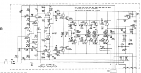
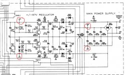
You can start buy checking the voltages at the 4 red circles i marked on the schematic
I you don't have a full schematic that you can post i have one on my thread
Start with the the power supply and regulator circuit. as bullittstang mentioned above
What tools equipment do you have access to? a decent Digital multimeter is a must.
You can start buy checking the voltages at the 4 red circles i marked on the schematic
Attachments
Last edited:
got 60v at green circle on both left and right channel but nothing at red spot. Between what do i measure that +67v ? and one more thing, i cant set the idle current, got nothing there on either side.
dc offset, measure between RL201 point and on o/p at the ribbon cable or?
dc offset, measure between RL201 point and on o/p at the ribbon cable or?
Attachments
Hello jesseewing sorry for my delay my internet was down
Have you read my post about my repair on my NAD 216? some good information from Mooly there as he said always best to work of the schematic not pictures
The +60v and -60 volt is supplying the amp boards with the correct rail voltage
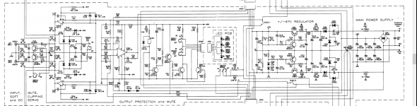
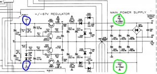
Now you need to check the other two voltages that is the regulator circuit the +67vdc and -67vdc volts you need to check them at the points i circled blue on the schematic on one leg or R212 and the anode side of D209 work off of the schematic i have marked there places in blue
If you don't have the correct voltages or only a good voltage on one side you have to start checking componits on that side of the regulator circuit. on my regulator circuit i had some bad/shorted capacitors.
You can start by checking R201 and R202 they are 1 watt 10 ohm fusible resistors i have marked them on the schematic in lime and are the start of the voltage regulator circuit. ''make sure to have the unit unplugged when checking the values of these as they are fed with AC voltage''
Don't worry about the dc offset or the idle current until you have checked the regulator voltages.
I have also included the full schematic in this comment for you
You can also grab the service manual here if you dont have it NAD 216 - Manual - Stereo Power Amplifier - HiFi Engine if you dont have just register for free
Have you read my post about my repair on my NAD 216? some good information from Mooly there as he said always best to work of the schematic not pictures
The +60v and -60 volt is supplying the amp boards with the correct rail voltage
Now you need to check the other two voltages that is the regulator circuit the +67vdc and -67vdc volts you need to check them at the points i circled blue on the schematic on one leg or R212 and the anode side of D209 work off of the schematic i have marked there places in blue
If you don't have the correct voltages or only a good voltage on one side you have to start checking componits on that side of the regulator circuit. on my regulator circuit i had some bad/shorted capacitors.
You can start by checking R201 and R202 they are 1 watt 10 ohm fusible resistors i have marked them on the schematic in lime and are the start of the voltage regulator circuit. ''make sure to have the unit unplugged when checking the values of these as they are fed with AC voltage''
Don't worry about the dc offset or the idle current until you have checked the regulator voltages.
I have also included the full schematic in this comment for you
You can also grab the service manual here if you dont have it NAD 216 - Manual - Stereo Power Amplifier - HiFi Engine if you dont have just register for free
Attachments
Last edited:
No worries, iam in no rush...been doing my own "research" on the amp while waiting...
ive measured +-67 voltage and i did get 85volts (on pin on R312 side and the other on D209) before doing this i checked the diod and it showed almost 700 on one side and over 1600 on the other side, wich should mean its broken ?
R201, 202 is OK cause i have replaced them earlier.
iam pretty sure all resistors in ok cause i tested them/compared to my other NAD216 working amp.
Hello again jesseewing i am not sure about your meaning (explanation) about the diode numbers 700 and 1600
Do you mean r212 and not r312?
I was hoping Mooly or someone would comment in this thread as i have a hard time understanding what others from other countries meaning or description.
The voltage +-85vdc is to high in my opinion. the two diodes D208 and D209 are zener diodes.
I am not sure were to tell you to start but on my NAD 216 i went through every component in the regulator circuit and found 6 bad capacitors.
With the black lead of the voltmeter on a good clean chassis ground use the red lead and measure the DC voltage at +VL and -VL wires on either of the power amp boards. You should read about +60 volts and - 60 volts on the +VL and -VL respectively.
With the black meter lead still on a good chassis ground, use the red lead to measure the DC voltages at pin 3 and pin 6 of JP203 or JP204. Pin 3 should be -67 volts and pin 6 should be +67 volts.
When you replaced R201, R202, R203, and R204, did you replace them with the proper *fusible* resistors? If not, that would be a safety.
Thanks Ylli very good recommendations thanks for stepping in and help guide the member as im a better learner than teacher ")
NOTE:
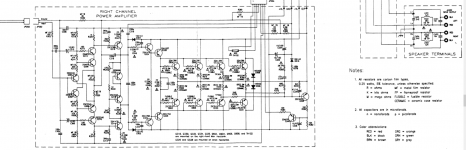
All of the blue resistors are 1% tolerance MF metal film type and need to be replaced with the same exact type and ohm/wattage rating. the service manual from hifi dot com is incomplete as stated with the specs of certain componits and you have to use the schematic.
Happy Holidays
NOTE:
All of the blue resistors are 1% tolerance MF metal film type and need to be replaced with the same exact type and ohm/wattage rating. the service manual from hifi dot com is incomplete as stated with the specs of certain componits and you have to use the schematic.
Happy Holidays
Last edited:
hey
sry for not specifying wich part i meant. The result was from measuring D209 but since its a zener diod the current can flow both ways and is OK then. (ty for clearing that out for me)
the only capacitors i swapped on the regulator board is C218 C219 cause i hade some leftovers.
iam checking diods now and found D214 on the regulator board to be broken (didnt get any reading what so ever)
and alot of non zendiods with readings on both sides,
With the black lead of the voltmeter on a good clean chassis ground use the red lead and measure the DC voltage at +VL and -VL wires on either of the power amp boards. You should read about +60 volts and - 60 volts on the +VL and -VL respectively.
With the black meter lead still on a good chassis ground, use the red lead to measure the DC voltages at pin 3 and pin 6 of JP203 or JP204. Pin 3 should be -67 volts and pin 6 should be +67 volts.
When you replaced R201, R202, R203, and R204, did you replace them with the proper *fusible* resistors? If not, that would be a safety.
i do have that + - 60 volts on both sides (58.5volts to be correct)
JP203 i measured almost 56volts and JP204 i measured 42volts
I´ve replaced R201, R202, R203, R204 with fusable resistors.
JP203 i measured almost 56volts and JP204 i measured 42volts
JP203 and JP204 are 'mirror' connectors. One for the right channel and one for the left. For power, they have the same power on the same pins.
Measuring at *either* JP203 or JP204, pin 3 should measure -67 volts and pin 5 should measure +67 volts.
Which pin measured only 42 volts?
Last edited:
JP203 56v at both pin 3 and 5
JP204 56v at pin 3 and 42v at pin 5
how can i get 67volts when its specified -56 and +56 volts on the powersupplyboard at JP204?
Are you sure you have a 216, because that voltage is a 214 amp.
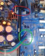
Check voltage on the links right infront of the Red, Green, Blue and I think Purple from the PSU board. That is straight from the PSU before any other protections. A 216 should yield +\- 67Vdc. Anything lower and we need to find where that voltage drop is
Last edited:
how can i get 67volts when its specified -56 and +56 volts on the powersupplyboard at JP204?
The schematic for the NAD 216 shows a +/- 67 volt supply. I'll assume this is indeed a 216.
Please measure and post the voltage at:
Cathode (banded end) of D206
Anode (unbanded end) of D207
Collector of Q201
Emitter of Q201
Collector of Q204
Emitter of Q204
Make these measurements with the meter negative lead on chassis ground.
- Home
- Amplifiers
- Solid State
- NAD 216 red protection problem