Thanks so much for getting back to me.
I have 66.8 V at R212 and -67.2 V at R217, my understanding is these should be 67 V not 55 V? (It's a NAD 216 not a 214)
I get +60.0 V and -59.9 V at J308 and J304 on the Right amp board (same for 305 and 309 on the left one)
Disconnecting all jumpers from power supply to amplifier does not get it out of protect mode, (stays red). This is disconnecting TH102, TH101 and the input lines.
Placing the red probe on the black stripe side of the diode
D213: 15.0V
D214: -0.66V
D215: 26.9V
D216: 27.5V
D214 doesn't feel right does it?
Looking at the schematic I see IC201A near it so I'll give you those voltages relative to chassis ground in case that's useful, all readings in V
P1:14.36
P2:0.068
P3:-0.003
P4:0.654
P5:-0.003
P6:0.061
P7:14.37
P8:15.12
The other side of R244 is -67.3V
R243 is 6.17 K
R244 is not giving me a reading
I'm not 100% sure how to measure the capacitor, do I need to desolder it?
if i put the probes across IC pin 3 and 4 (should be equivalent to the capacitor right?
C230 gives me 0.22nF on capacitor setting and ~30M ohm on resistor setting, it then counts down its resistance, i.e. 10 seconds later it is saying 20Mohm
On continuity mode I do not get a beep across D214 (I do get a very short one when I first put it on), so I presume it is not short circuited? on diode mode it gives 0.57V one direction, "0L" the other direction
I just held a 1/8W 5.1K resistor across R244 (its all I had) and the amp went green! The resistor started warming up and I turned it off, but I assume that's just because A. it's the wrong value and B. it's too small. Next steps I guess is to swap that bad boy out for a new one
R243 and R244 both dissipate 0.5 Watt. It is never a good idea to run a resistor at rated power because it will get very hot. You had one resistor drift high in value and the other opened. They should both be replaced with the largest body resistor that will fit in the board. Hopefully the rating that fits is at least 1 Watt. Use two Watt resistors if they fit.
Oh shoot, Sorry Bill I didn't see your message
I popped into the store and have swapped out the offending resistor with A 0.5w version. I guess the last one survived almost 30 years, so it should be alright for a while... [edit, actually its quite a bit warmer than the other one, I read 0.5W as it wanted a 0.5W but if as you say it means it dissipates 0.5W then that makes sense, the other one is bigger and I just assumed it was newer technology. I'll place an order for some 1W versions . My local store doesn't have anything bigger]
It's up and running now though (Haven't yet tested under load.)
Thanks so much for your help "Audio Service"
Last edited:

First, say Thanks this is a great forum. thanks, Sqeek, Ylli, Audio service, and everyone for the post.
I have a NAD214 of the amplifier. My amplifier had the same problem. The amplifier was in protection. I knew the model close to Nad216, just different the output power. I study all the feedback about check the amplifier's Led red in protection. I test
IC202(TA7317P)
Pin1 0.68-0.69V
Pin 2 0 V
Pin 3 0V
Pin 5 0.78V
Pin 6 50 V ( the relay turn on or off, I don't know)
Pin 7 0.04V
Pin 8 0.38V
Pin 9 0.44V
Compare the TA7317P data
Pin 8 and Pin 9 have a problem. the normal voltage is Pin 8, 8V, and Pin 9, 3.1V.
Test:
D213 15V
D214 15V
R244 -55V
R243 55V
Based on previous the post mentioned the Pin 8 OF IC202 that offers the protection signal.
I thought the relay or TA7317P was broken. I purchase the parts after I wish I can find out the problem. I am not an Electrical Engineer。
/Users/foxben/Downloads/IMG_2511.HEIC
/Users/foxben/Downloads/IMG_2512.HEIC
I had a problem with a 214 with intermittent problems. I turned out to be the tarnished connectors between the Power board and one of the amp boards. My amp had plugs that made bad contact. Some people remove the plugs and solder the ribbon cable directly to the amp boards. Maybe it your problem as well.
Attachments
thank you for your response. I have been pulled out the plug and put it in several times, and tested the signal with the L-channel and R-channel. I am sure not the plugs problem.
An externally hosted image should be here but it was not working when we last tested it.
 Ben99, your posts are currently under moderation as you are a new member. There is no need to post multiple times, it will just take a little time for them to show up.
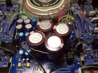
Im back....Your photograph shows brown glue used during manufacture it is not the capacitor leaking.
Can you check the plus and minus 55 Volt rails are present?
Plus 55 Volts should be present on one end of R212 and Minus 55 Volts should be present on one end of R217
If the voltages are present can you disconnect the left and right Amplifier modules, then power on the Amplifier and check if the LED turns green and the speaker protection relay turn on after approximately 5 seconds.
If the LED goes green and the relay operates switch off the Amplifier and connect the right channel module and repeat the test.
If the LED goes red, again turn off the Amplifier disconnect the right channel module and then connect the left channel then repeat.
You should be able to quickly verify if you have an issue with either module causing the Amplifier to switch to protection.
Unfortiunately my amp has fallen back into disrepair.
We now have a very weak distorted output instead of the nice loud sounds it should be making.
Interestingly I thought I'd look back at this thread and start with this advice. However, where I'm now at us
- Power on, light goes green, distortion comes out.
- Remove either amp board, we now turn on into speaker protection mode
- R206 starts smoking
- Connect the amp boards back on and we're back to the distortion
Can you check voltages further up the power supply chain? unlikely that the transformer or bridges are bad, so I am guessing either a resistor has gone open or one of the diodes or transistors has gone bad.
These were on my spreadsheet of parts replacements when I rebuilt a 216 4-5 years ago - D101, D102, D213, D214, Q204, R212, R217 (don't remember if both these resistors were bad, but they run very hot, so I changed them both). I then replaced the outputs on one channel (one output was shorted C-E) and recapped both amp boards capacitors (there was only one bad cap, a few were slightly out of spec.), but replaced them all since I had it all apart already.
Hope you figure it out and get it running again - very nice amplifier IMO
- Home
- Amplifiers
- Solid State
- NAD 216 red protection problem