")
Cathode (banded end) of D206 = 2.071v
Anode (unbanded end) of D207 = 1.037v
Collector of Q201 = 1.3mV
Emitter of Q201 = 2mV
Collector of Q204 = 7.8mV
Emitter of Q204 = 6mV
Is the unit plugged in and turned on? These measurements need to be made on a unit that is powered on. And be sure your meter is set to measure DC volts.
Just something I ran across years ago. I had a Nad power amp that wouldn't come out of protection. Turned out it was a bad solder joint on one large resistor,can't remember which one.I found it by pulling on the ends of all the large resistors on the board.I've had that happen as well on a television set.Large resistors generate heat and many power cycles can cause solder joint problems.
Is the unit plugged in and turned on? These measurements need to be made on a unit that is powered on. And be sure your meter is set to measure DC volts.
i assumed it should be powered off, but i need to get longer pins for my multimeter cause i cant get to Q201 with the standars lenght due to narrow space.
Possible to measure without the two ribbon cables JP203/204 plugged in? if so its possible to flip the board.
Possible to measure without the two ribbon cables JP203/204 plugged in? if so its possible to flip the board.
Yes, for these measurements can be made with JP203/204 unplugged.
Cathode (banded end) of D206 = 113v
Anode (unbanded end) of D207 = -114v
Collector of Q201 = .037v
Emitter of Q201 = .033v
Collector of Q204 = 42.7v
Emitter of Q204 = 42.7v
when i measured Q204 with the board flipped over i got the same result as Q201 so the result on Q201 might not be so reliable.
Anode (unbanded end) of D207 = -114v
Collector of Q201 = .037v
Emitter of Q201 = .033v
Collector of Q204 = 42.7v
Emitter of Q204 = 42.7v
when i measured Q204 with the board flipped over i got the same result as Q201 so the result on Q201 might not be so reliable.
If you changed the caps in this unit, then double check that you have the polarity of C212 and C213 correct.
The voltages at D206 and D207 are good, but the voltages on Q201 and Q204 are not what would be expected. The voltages on Q201 and Q204 collectors should be only a few volts less than what you measured at the diodes. With power off, use your ohmmeter to check R203, R204, R205, and R206.
Do you have a dim bulb tester (DBT)? It's just an extension cord with a light socket in series that you can put an incandescent light bulb in. That acts as a current limiter. May need to do that to prevent further damage downstream as we continue to work through the supply.
R203 = 330ohm
R204 = 330ohm
R205 = 97.8ohm
R206 = ??? number keeps jumping up and down here, could not get a good reading on either side of the board.
i dont have a bulb tester and i have not swapped C212/C213...it was C218 & C 219 and iam positive that polarity is correct there.
R204 = 330ohm
R205 = 97.8ohm
R206 = ??? number keeps jumping up and down here, could not get a good reading on either side of the board.
i dont have a bulb tester and i have not swapped C212/C213...it was C218 & C 219 and iam positive that polarity is correct there.
The numbers still aren't making sense. If you have +113 volts at the cathode of D206, and 0 volts on the collector of Q201, you are dropping 113 volts across 430 ohms. That would dissipate 30 watts of power. Those resistors (R203, R205) would have gone up in smoke.
Again, I don't have any pictures of the insides of this... can you get to R203, R204, R205 and R206 with your voltmeter with power on? If so, measure each of these with the negative lead on chassis ground and post results.
Again, I don't have any pictures of the insides of this... can you get to R203, R204, R205 and R206 with your voltmeter with power on? If so, measure each of these with the negative lead on chassis ground and post results.
Found a more complete service manual. The resistor I have been calling R206 might actually be R208. Looks like 206 on the schematic, but is definitely R208 on the layout drawing.
With the exception of R206 (and I have probably been asking for the wrong resistor there), those number look OK. Let's look again at the +/- 67 volts busses.
There are two jumpers on the board just below the connector in your picture. One is labeled J227, and I think the other is J228. Please measure the voltage on these jumpers to ground.
Last edited:
R208 should be the equivalent of R205, except on the negative regulator. It needs to be about 100 ohms. If it is measuring 800k, then it needs to be replaced.
[To confirm the identity of this resistor - one end is connected to Q204 collector, and the other end is connected to R204/R209/C213.]
[To confirm the identity of this resistor - one end is connected to Q204 collector, and the other end is connected to R204/R209/C213.]
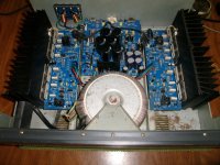
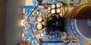
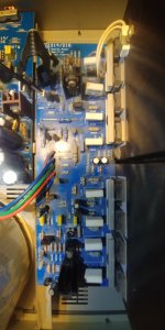
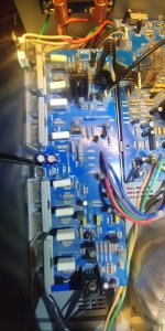
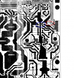
Thanks Sqeek. I don't know why I didn't download the whole manual earlier, I've been working off the earlier posted schematic. Got the full SM now.I thought i would share a high resolution photo of the inside of my NAD 216 if needed
Found a more complete service manual. The resistor I have been calling R206 might actually be R208. Looks like 206 on the schematic, but is definitely R208 on the layout drawing.
With the exception of R206 (and I have probably been asking for the wrong resistor there), those number look OK. Let's look again at the +/- 67 volts busses.
There are two jumpers on the board just below the connector in your picture. One is labeled J227, and I think the other is J228. Please measure the voltage on these jumpers to ground.
J226 = 153,8v
J227 = 41,3v
So the voltage at the blue circled point (J226) is 158.3 volt and on the red circled point (J227) you measure -41.3 volts.
Earlier you measured the voltage at the collector of Q201 as 105 volts. I'm at a loss to understand how you can have 105 volts at the collector of Q201 and 158.3 volts on the emitter.
Let's try this...
Set your meter to read DC volts. If it needs to be set to a particular range, select the 200 volt range. Connect the negative (black) lead securely to system ground. This is the 0 volt buss, and should be connected to the chassis. Otherwise, J212 looks to be a ground jumper and can connect there. You may chose a different ground point, but if you do please let me know where you are connecting the black lead.
Now, with power on, using the red lead of the voltmeter and being careful not to short anything, please measure the voltages at:
Q201 collector - that is the center lead
Q201 emitter - that would be the left side lead
Q201 base - the right side lead
Q204 collector - the center lead
Q204 emitter - the left side lead
Q204 base - the right side lead
If the voltage on the meter shows with a negative sign, please include that when posting.
Attachments
Q201 collector -
Q201 emitter -
Q201 base -
Could not get any reading on any pin at Q201 from the back side (cant reach it at the front side) but i solder the transistor loose from the board and its working as it should be for a NPN
J226 = 68v
J227 = -68v
hade some difficults with this reading but i think i got it right this time.
Q204 collector = -102v
Q204 emitter = - 67,4v
Q204 base = -68,7v
As ground iam using the chassi to connect the black lead.
"i do have that + - 60 volts on both sides (58.5volts to be correct)"
Very good
"J226 = 68v
J227 = -68v"
Exactly what it is supposed to be.
So it looks like the power supply is operating properly. Your original problem, posted back on page 1:
"When i try to start the amp it never switches from red to green as it suppose to and the red protection lamp constantly lights."
Let me study the protect circuitry and I'll post back.
- Home
- Amplifiers
- Solid State
- NAD 216 red protection problem