Hi folks
I found this interesting all JFET topology:
In this paper from 2014:
https://www.ijareeie.com/upload/2014/september/20_Small_Signal.pdf
Has anyone built anything like this as an audio amp?
I was thinking it might make an interesting headphone amp using something like the BF862 or a higher power version using the LD1010D.
Attachments
More important points, are that there are now very few available JFETs and PN4393 is obsolete or rather, it's no longer produced cheaply in high volume. The price of guaranteed replacement product from Central Semi or Linear Systems, is around US $1-2 ea. in small quantity - if currently in the distributor's stock. Goodness knows what you will receive if you gamble with Ebay type sources where there are no quality or performance guarantees beyond the obvious visual checks. As another matter of concern to JFetters, BF862 is also obsolete .
The reason for choosing 2N/PN4393 for the application in the paper was the very high overall gain possible but this is limited to low output current. This particular transistor type isn't really suitable for a power amplifier - not even for hifi headphones so you would need to add a buffer transistor or BJT stage anyway which kinda defeats the purpose of having all that unnecessary current gain. rds = 100R and Idss = 5-30 mA max.
ex-Fairchild's J111 FETs are said to have similar characteristics.
HTTP 301 This page has been moved
HTTP 301 This page has been moved
Last edited:
Hi Ian
I have to confess to not knowing much about how the circuit works, hence I thought I'd ask.
You're absolutely right about the scarcity and cost of JFETS, there are still some types available in SOT-23, I just soldered a bunch of J177 P channel JFETS onto SOT-23 adapter PCBs, not too easy, but with practice, doable. J310 seem quite cheap and easily available in SOT-23, as an N channel device, but of course, these are low power devices.
Of course,it's a different story with MOSFETs, there are a bewildering array of types, due to their use in switching applications and they are still cheap.
My small collection of JFETS includes N channel devices: 2N5485, 2SK246, 2SK30A, BF256B and BF862, but only a half dozen or so of each, they are intended for a couple of Zen I/V converters and a couple of buffers I'm working on, I'll have some left over most likely but none of them strike me as all that suitable for this triple darlington circuit.
I do have a few LD1010Ds, which can dissipate upto 85W, but it sounds like this circuit isn't workable without major changes.
The low output current would mean needing to add something like a diamond buffer or a Pass B1 as an output buffer stage?
I thought this topology would be interesting to play with as a headphone amplifier, but it sounds like it has too many issues, sadly.
Last edited:
> not knowing much about how the circuit works
I know a lot of circuits. This one makes no sense. Ca ensures no audio gets to J2 J3. Rsr is so large nothing in this leg can have much effect on anything. And thumb-counting gate voltages says J2 J3 are cut-off.
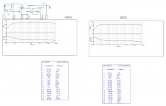
The voltage gains, bandwidth, and THDs seem typical for a ONE device amplifier.
The report only mentions SPICE work. When a circuit defies common-sense analysis it would be good to show data from an actual example. The exact JFET should NOT be critical; re-bias should get comparable results.
And yet SachchidaNand Shukla does appear to be a noted Professor with published research going back decades. I do not know what to make of this. Typos in text and drawings?
I know a lot of circuits. This one makes no sense. Ca ensures no audio gets to J2 J3. Rsr is so large nothing in this leg can have much effect on anything. And thumb-counting gate voltages says J2 J3 are cut-off.
The voltage gains, bandwidth, and THDs seem typical for a ONE device amplifier.
The report only mentions SPICE work. When a circuit defies common-sense analysis it would be good to show data from an actual example. The exact JFET should NOT be critical; re-bias should get comparable results.
And yet SachchidaNand Shukla does appear to be a noted Professor with published research going back decades. I do not know what to make of this. Typos in text and drawings?
You may find this introductory Wiki nails it sensibly and points out the real and important requirements to focus attention on: Headphone amplifier - WikipediaI thought this topology would be interesting to play with as a headphone amplifier, but it sounds like it has too many issues, sadly.
DiyAudio also has a forum here that's dedicated to headphone amps, as you may already be aware, so I'd read there for a bit there before giving up your ideas entirely - there's always someone out there who is thinking along similar lines to yours and maybe has come to different conclusions. that's when you learn interesting and useful stuff.
https://www.diyaudio.com/forums/headphone-systems/
I get a lot of value from wrenchone's threads there and in the Line Level (preamps) Forum, where I've learned a bit about linear applications for JFETs and what the specs mean, myself
")
Last edited:
Hmm, so this triple circuit is a load of crap, interesting.
I'm working on a couple of headphone amplifiers, both use jfets to drive mosfets, using designs by members of this forum, so I don't really need to add any more builds right now, I just found this unusual triple circuit interesting so figured I'd gather some opinions on it.
I'm working on a couple of headphone amplifiers, both use jfets to drive mosfets, using designs by members of this forum, so I don't really need to add any more builds right now, I just found this unusual triple circuit interesting so figured I'd gather some opinions on it.
Excuse me, but I think this amplifier is a flop. Place a large capacitor across RA in fig. 1 and you'll have an amplifier with a gain of about 20. The purpose of J2 in fig 2 must be to have an excuse for one more paper to publish… This would be obvious if you look at fig.4 where the current source and rd2 for J2 is shorted.
Hi Ian,
Before bashing academia as a whole please consider that not all published papers have equal scientific value even if there are available online in pdf format. The intrinsic value can be assessed using bibliometric factors such as the journal impact factor (IJAREEIE at ~0.4 is bottom scale) and the number of citations for this actual paper in other published works (a single citation since 2013 according to Google Scholar which means very poor in layman’s terms).
Before bashing academia as a whole please consider that not all published papers have equal scientific value even if there are available online in pdf format. The intrinsic value can be assessed using bibliometric factors such as the journal impact factor (IJAREEIE at ~0.4 is bottom scale) and the number of citations for this actual paper in other published works (a single citation since 2013 according to Google Scholar which means very poor in layman’s terms).
...IJAREEIE at ~0.4 is bottom scale....
There is some "racism" involved. Folks in other countries do not usually turn to India for information. There IS some good work happening there, and we should accept that.
However IJAREEIE is "pay for publication". While this reflects the brutal economics of publishing today, there is the suspicion that if your $70 payment goes through (and more if you want a copy) they may be reluctant to refuse your paper. I do not know how that really works out; I have not been near academic publising in a very long time, and in a different field, and debugging a database not looking at papers/authors.
hi koko, I think that You missed Rd in the sch from +18V to drain of J3? So the drain is left open...
Increase C2 to 10uF for proper BW in low end, and add some grid stopers for cutout the ultrahigh and prevent oscilations. Also consider the larger value of Ca bypass C at the 250ohm Ra J1 source network. Should be much larger...
cheers
Increase C2 to 10uF for proper BW in low end, and add some grid stopers for cutout the ultrahigh and prevent oscilations. Also consider the larger value of Ca bypass C at the 250ohm Ra J1 source network. Should be much larger...
cheers
> not knowing much about how the circuit works
I know a lot of circuits. This one makes no sense. Ca ensures no audio gets to J2 J3. Rsr is so large nothing in this leg can have much effect on anything. And thumb-counting gate voltages says J2 J3 are cut-off.
The voltage gains, bandwidth, and THDs seem typical for a ONE device amplifier.
The report only mentions SPICE work. When a circuit defies common-sense analysis it would be good to show data from an actual example. The exact JFET should NOT be critical; re-bias should get comparable results.
And yet SachchidaNand Shukla does appear to be a noted Professor with published research going back decades. I do not know what to make of this. Typos in text and drawings?
I agree. I think if this circuit works, it is only J1 that does anything. J2 drives the open circuit gate of J3, which would be saturated except the source Rsr resistor is 250k (huge) so it is only a minor short.
Note "RL=10K", ie not suitable for headphones.
Maybe I should investigate more but this looks fraud an/or stupidity to me. If you want a headphone amp, I suppose you could complicate it like that Ausy chick who wants 1ppm distortion, but because you are not dealing with expensive high power stuff, it's very easy. Just get a good dual op-amp and buffer it. The op-amp supply limits are just fine for headphones. Or a ~5 transistor amp can sound very good, ie diff-amp, VAS and one stage of complimentary followers. There are also chip amps intended for music players, a perfect match. Learn to read data sheets and build the application circuit(s), or start with a Chinese board. Have fun!
- Status
- This old topic is closed. If you want to reopen this topic, contact a moderator using the "Report Post" button.
- Home
- Amplifiers
- Solid State
- JFET Triple Darlington Amplifier