Bridging with two current sources in series is not feasible, for even a slight difference in the currents will bang the load to the supply rails. To use bridging in current drive, the other half has to be a voltage amp that preferably only mirrors the potential of the other side. The result is still current drive. Keeping the whole stable is more demanding than with a single amp, but it can be done.
That is a really good point ETM, and something I overlooked. Why use two current drivers.. 
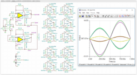
When simulating these things one tend to use equal values and these things does not show up. I have tried a simulation with a 5% error in the current resistor and that gives a huge imbalance in the voltage from each side as can be seen on the attachment. I will start working with an inverted voltage follower as you suggested. Thanks for the tip.
When simulating these things one tend to use equal values and these things does not show up. I have tried a simulation with a 5% error in the current resistor and that gives a huge imbalance in the voltage from each side as can be seen on the attachment. I will start working with an inverted voltage follower as you suggested. Thanks for the tip.
Attachments
That's absolutely true.
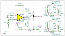
The right side of image in #29 did exactly what ETM suggest, mirroring the other side.
This setup is not prone to any such sensitivities.
And the ADA4870 (not ADA4780) that you suggest is a very nice component.
With 8 of them you can drive 4 Amp through an 8 Ohm load.
Hans
The right side of image in #29 did exactly what ETM suggest, mirroring the other side.
This setup is not prone to any such sensitivities.
And the ADA4870 (not ADA4780) that you suggest is a very nice component.
With 8 of them you can drive 4 Amp through an 8 Ohm load.
Hans
It is certainly a valid point. I have suggested to measure current in just a single point, and to feed it back to both output stages. The important thing is that both output stages run at the same voltage.
Making a current drive amplifier in theory is no problem. What I think we should focus on is how to handle likely loads that might drive the amplifier far beyond its operating point.
If someone has an expensive compression driver, and they have added a serial capacitor to protect it, that could lead to uncontrolled voltage at low frequencies.
This really depends on how ideal current source we want to run this amplifier at. If we run it as just a voltage drive amplifier with a few ohms of output impedance, we are safe, but we have hardly achieved our goal.
Maybe you can clarify why it is so important to have a balanced-bridged solution.It is certainly a valid point. I have suggested to measure current in just a single point, and to feed it back to both output stages. The important thing is that both output stages run at the same voltage.
A main amp with a balanced input, usually has the speaker between hot and ground. Only up to a certain point the thing is balanced.
So why not simply put a balanced circuit at the input, giving you the high CMRR and forget about a very complex to handle balanced part providing the power.
The circuit in #29 doesn't have one single critical precision part.
1) What happens with a current amp when the driver is disconnected ?Making a current drive amplifier in theory is no problem. What I think we should focus on is how to handle likely loads that might drive the amplifier far beyond its operating point
If someone has an expensive compression driver, and they have added a serial capacitor to protect it, that could lead to uncontrolled voltage at low frequencies.
This really depends on how ideal current source we want to run this amplifier at. If we run it as just a voltage drive amplifier with a few ohms of output impedance, we are safe, but we have hardly achieved our goal.
Almost nothing. No power is supplied and hardly anything can go wrong.
2) The inductivity of the driver could cause the output voltage to go beyond its supply voltage.
A few Schottky diodes from output to supply can prevent this from happening.
3) And the possible cap you mention in series with the speaker ? Seemingly harmless.
A HP filter at the input can block very low frequencies.
4) And to reduce inductivity increasing the risk of oscillation, a Zobel network across the speaker may be added.
5) Then you have the driver to take care off.
With a (relatively simple) protection circuit in parallel to the speaker, one can set this to the required parameters, like maximum voltage, for a certain time or even frequency dependant.
But all this can be added once the final design has been settled.
Hans
Maybe you can clarify why it is so important to have a balanced-bridged solution.
A main amp with a balanced input, usually has the speaker between hot and ground. Only up to a certain point the thing is balanced.
So why not simply put a balanced circuit at the input, giving you the high CMRR and forget about a very complex to handle balanced part providing the power.
A symmetrical amplifier can basically work off the ground, or at least with extremely high ground impedance, and therefore give superb CMRR without the need for any precission components.
The circuit in #29 doesn't have one single critical precision part.
This circuit has virtually no CMRR at all. This needs to be added and that will eventually cost us a fair bit of noise.
1) What happens with a current amp when the driver is disconnected ?
Almost nothing. No power is supplied and hardly anything can go wrong.
The voltage rises, and the amplifier will go into clipping. But the current goes to zero. What is more interesting is what happens if you re-connect the driver while the amp has full output voltage. The easiest way to determine this is probably to measure it on a prototype amplifier.
2) The inductivity of the driver could cause the output voltage to go beyond its supply voltage.
A few Schottky diodes from output to supply can prevent this from happening.
Once the amp is about to go there, we probably already have a problem we should have prevented at an earlier stage.
3) And the possible cap you mention in series with the speaker ? Seemingly harmless.
A HP filter at the input can block very low frequencies.
I did test this. 10µ on a 4 ohm load. 100Hz square wave. With pure current drive the amp goes up to about 8kV p-p. If I short out the cap, it goes down to a nice 20V square wave.
4) And to reduce inductivity increasing the risk of oscillation, a Zobel network across the speaker may be added.
Absolutely, but it would be very nice if something like this could be optimized automatically to the load.
5) Then you have the driver to take care off.
With a (relatively simple) protection circuit in parallel to the speaker, one can set this to the required parameters, like maximum voltage, for a certain time or even frequency dependant.
Again, this should work smoothly, and quickly enough, without interfering with the signal or the drive mode. And this should ideally happen automatically.
But all this can be added once the final design has been settled.
Hans
Given the information we have, I think it would be even more interesting at this point to figure out what the effects of different high output impedances would be. For example, what is the difference between 10 and 50 ohms, or 500, or 10k. And are there situations where seriously high output impedance really would be required to achieve the benefits of a current drive amp?
This is really important in order to know what kind of safety and protection circuits would be needed.
There is something odd. It seems to mirror the sensing resistor voltage rather than the load's.Hans Polak said:The right side of image in #29 did exactly what ETM suggest, mirroring the other side.
Any offset current will already fill up such a capacitor, even without signal. Other means of protection should be sought then.Snickers-is said:If someone has an expensive compression driver, and they have added a serial capacitor to protect it, that could lead to uncontrolled voltage at low frequencies.
___
The voltage amp side doesn't need to be high precision; it is enough that it approximately balances the output potentials. The current is still controlled solely by the current side.
Oops, you are right.There is something odd. It seems to mirror the sensing resistor voltage rather than the load's.
The second amp was doubling the current instead of doubling the maximum voltage across the Speaker.
Here is the corrected version.
Hans
Attachments
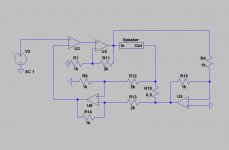
Nice to see a thread going on this. If you have not seen it, there is a great book dedicated to the current drive of loudspeakers. Current-Drive - The Natural Way of Loudspeaker Operation I have experimented with the LM3886 chip amp. Using a 0.5 ohm resistor in series with the speaker ground for current sensing and directly attaching this node to the negative input of the amplifier rather than the voltage divider worked fine. I also found that a line level Linkwitz transform solves the low damping issue for the driver low frequency resonance very nicely. I look forward to trying out some of the circuits you have shown here.
And guess who’s the Author, yes that’s ETM.Nice to see a thread going on this. If you have not seen it, there is a great book dedicated to the current drive of loudspeakers.
Hans
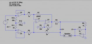
And based upon the topology that Armand used, here is a balanced and bridged version.
Keeping R1,R2 and R6,R7 within 0.1% (see image below), CMRR is 70dB over the whole FR range.
CM input impedance 1Meg, DM input impedance 50K.
U2 and U3 could be composed of a number of ADA4870 OPA's.
Just a generic design, not yet with protection measures.
Hans
Keeping R1,R2 and R6,R7 within 0.1% (see image below), CMRR is 70dB over the whole FR range.
CM input impedance 1Meg, DM input impedance 50K.
U2 and U3 could be composed of a number of ADA4870 OPA's.
Just a generic design, not yet with protection measures.
Hans
Attachments
Current drive: I don’t see this resulting in good sound. Speaker designs are usually optimised for low Z voltage drive. High Z drive will screw up the f response and damping.
It would have been nice if you did read the few posts prior to you in this tread. Then you would have understood that an amplifier like this is not intended for use with a finished speaker.
And based upon the topology that Armand used, here is a balanced and bridged version.
Keeping R1,R2 and R6,R7 within 0.1% (see image below), CMRR is 70dB over the whole FR range.
CM input impedance 1Meg, DM input impedance 50K.
U2 and U3 could be composed of a number of ADA4870 OPA's.
Just a generic design, not yet with protection measures.
Hans
I do find the circuit interesting. However, 70dB CMRR is not an impressive figure. Off course it could be improved by increasing the precision of R1,2,6 and 7. But those resistors are also a source to noise. That is the reason for my desire to make this a balanced amp.
Why not just control U3 via the input signal?
So, let's just say that 100% current drive is not realistic, and that when we convert the current sense feedback into voltage, we could, if we have a signal that can drift to compensate, feed the same correction to both halves. So the two halves are fed by a signal that simply lets the entire circuit drift off to make it perfectly symmetrical at all times, and that both halves then effectively could control at least 90% current and 10% voltage.
The idea is that any conflict will not cause pumping, but instead a CM drift that the speaker will not react to anyway.
And guess who’s the Author, yes that’s ETM.
Hans
A small world. At least the world of current drive amps. That probabaly describes the size of the market as well

Yes. It might be an idea to edit your first post to include your intention of only using it above resonance. I have read the whole thread, many people don't, and as it lengthens that will probably become more prevalent.It would have been nice if you did read the few posts prior to you in this tread. Then you would have understood that an amplifier like this is not intended for use with a finished speaker.
- Home
- Amplifiers
- Solid State
- High performance current drive power amplifier