")
The resistor came over night and has been installed idle current set @ 18mv per the service manual offset checked .006 mv both sides and and it is playing as i type i want to thank Mooly for the great help,information and his time and for keeping it straight and to the point
Well i got out my pre-amp and hooked it up and got a huge scare right of the bat as the volume is stuck on full and it wasnt a pretty sound it blasted the amp and speakers twice before i could get to it as i had it on the radio (another mistake i should have had the preamp source output on a non working output at first ) another lesson learned.
I had hooked up my polk monitor 7's (dumb mistake) as i was going to hook up some 8ohm small front 5.1 channel speakers but i got cocky (don't do this ) use a speaker you don't care about running/losing at first start up after a repair
Well my speakers are ok i have a denon cd player with a volume so i used that for the amps input and everything is working like it should
Now to tear this preamp down and have a look at the volume control
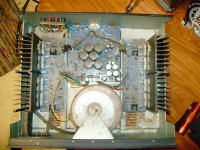
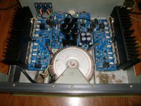
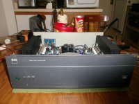
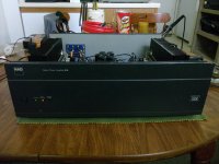
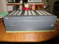
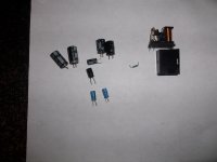
Thanks Again Mooly and the others for there input i hope this post might help others with this amp i am posting some pictures the very first one is how it looked when i got it and the rest are after it was done the last are the parts that were replaced
Happy Holidays to everyone
Well i got out my pre-amp and hooked it up and got a huge scare right of the bat as the volume is stuck on full and it wasnt a pretty sound it blasted the amp and speakers twice before i could get to it as i had it on the radio (another mistake i should have had the preamp source output on a non working output at first ) another lesson learned.
I had hooked up my polk monitor 7's (dumb mistake) as i was going to hook up some 8ohm small front 5.1 channel speakers but i got cocky (don't do this ) use a speaker you don't care about running/losing at first start up after a repair
Well my speakers are ok i have a denon cd player with a volume so i used that for the amps input and everything is working like it should
Now to tear this preamp down and have a look at the volume control
Thanks Again Mooly and the others for there input i hope this post might help others with this amp i am posting some pictures the very first one is how it looked when i got it and the rest are after it was done the last are the parts that were replaced
Happy Holidays to everyone
Attachments
 I'm really pleased you have fixed this. A high value resistor failing open circuit would be way down the usual list of suspects in something like an audio amp... so well done again.
Thank you so much Mooly for without your kindness and giving spirit this would have been much more troublesome and without your guidance and knowledge dam near impossible for some one of my level.
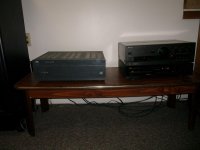
Well I put that dam preamp up got out my Technics SU-G70 with a bad svi chip its equipped with pre in/outs (preamp still good) and hooked it up to the NAD and it works just fine good combination actually , not a issue one with amp even while having the soft clipping engaged. i like this amp it is powerful runs cool and its solid and can hit very hard if need be. no complaints.
I would like to say that i thoroughly enjoyed working on this project and i find this amps design interesting and simple although its safety measures as i call them (protection and mute circuits) are a bit complicated it works i would welcome anyone's input on the regulator circuit improvements/modifications thing is there tied into the protection circuit if you feel the challenge and have ideals please tag me in the thread
for anyone that it might interest while checking the main pre and out put transistors they all had almost the same readings beta matched pretty dam good imo. well done NAD
Attachments
Last edited:
Thanks for the kind words. Its always good when you get a definite fix on some faulty gear.
The regulators in the NAD are a very low current design, and as such the performance is perfectly suited to the task they have to perform. All you could realistically do is to make sure all the electrolytics related to the regs are top quality parts. Don't change or alter values. Some might also change the IN4003 rectifiers for a faster soft recovery type diode but I suspect any perceived improvement from those would be more down to the satisfaction of changing them rather than a real difference.
The regulators in the NAD are a very low current design, and as such the performance is perfectly suited to the task they have to perform. All you could realistically do is to make sure all the electrolytics related to the regs are top quality parts. Don't change or alter values. Some might also change the IN4003 rectifiers for a faster soft recovery type diode but I suspect any perceived improvement from those would be more down to the satisfaction of changing them rather than a real difference.
Ok Thank you again Mooly that makes complete sense about the regulator design
I will most likely replace the 6 older capacitors left in the regulator circuit ( i have already sourced them) even though they tested good (two are Elco i think they are called and they make me a little nervous lol) just for piece of mind if anything.
The rectifiers i will leave alone i think as i feel kinda like you do about them.
I am jumping into refoaming a pair of Realistic Mach two's woofers and midranges once that project is complete then i will focus back to the NAD and replacing the capacitors with new ones.
Happy Holidays
Last edited:
Today my NAD 216 went into protection mode after half an hour listening to music and I noticed that left channel was too hot so I opened it on the bench with no load and checked voltage between TP301 TP303 with DVM and found it way out of specs reading 176mV instead of 18mV, I adjusted VR301 to get the right value of 18mV between TP301 TP303 and turned it off to let it cool down.
After some time that I turned it on again to take another measurment I noticed driver transistor Q325 which is a 2SC4793 running too hot, it was so hot that I couldn't touch it even though the amp hadn't be running for more than 5 minutes.
Any ideas about what can the problem be and what components should I test as I didn't have the time then and left it for a later inspection?
Today my NAD 216 went into protection mode after half an hour listening to music and I noticed that left channel was too hot so I opened it on the bench with no load and checked voltage between TP301 TP303 with DVM and found it way out of specs reading 176mV instead of 18mV, I adjusted VR301 to get the right value of 18mV between TP301 TP303 and turned it off to let it cool down.
After some time that I turned it on again to take another measurment I noticed driver transistor Q325 which is a 2SC4793 running too hot, it was so hot that I couldn't touch it even though the amp hadn't be running for more than 5 minutes.
Any ideas about what can the problem be and what components should I test as I didn't have the time then and left it for a later inspection?
Check your speaker teriminals for a DC offset... probably quite a large one.
Q325 is a driver transistor for the output stage. Someplace between it and your speakers you've got a shorted component.
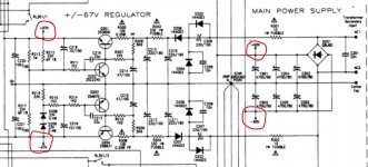
Schematic Diagram - Nad 216 Service Manual [Page 9]
I forgot to mention but there is no DC offset, the amp goes into protection mode because of left channel overheating.
The protection relay is pulling in?
With the amp on, carefully check on the relay pins, output transistor side of the contacts or at the junction of R363 and R365 which are the ceramic resistors in the output chain.
Check the schematic link I gave you...
My best guess is that you have a bad output or driver transistor.
Thanks Douglas, I already have the schematic printed, just came home and started checking components.
When I power up the amp it goes into normal operation as usual, yesterday night it went into protection mode after half an hour of listening to music and after I turned it off to let it cool it powered up again normally, that is when I noticed left channel overheating and opened it to check the bias.
The relay works normally.
Are you able to monitor the bias as the unit heats up? Is it staying at 18mV at idle even when warm, or is it changing? Did you see any burnt resistors, or bulged caps (C333/C333 - I have had those blow)?
I had to replace the bias pot on my amp, because it was sticking - go from 10mV to 35mV and no in between?
I had to replace the bias pot on my amp, because it was sticking - go from 10mV to 35mV and no in between?
I'm an amateur, but my next step would be to take some voltage checks from Q325, Q327, Q321 and Q323 (are these getting warm too?) to see where the over-voltage and heat might be coming from. Then work backwards until you get normal voltages or current.
Check current across R347 and R349.
Check current across R347 and R349.
Thanks Douglas, I already have the schematic printed, just came home and started checking components.
When I power up the amp it goes into normal operation as usual, yesterday night it went into protection mode after half an hour of listening to music and after I turned it off to let it cool it powered up again normally, that is when I noticed left channel overheating and opened it to check the bias.
The relay works normally.
It's not about the relay... it's about getting access to the output of the amplifer before the relay contacts, so you can check for DC offsets.
Might i suggest not jumping around i would start with the power supply voltages +60v and -60v and regulator voltages +67v and-67v
Don't just go throwing parts at it until you have made sure the supply voltages are correct. (on my regulator circuit i had many bad caps i have since replaced them all)
If all is fine move to the amp boards they are mirrored so you can check them with each other when checking componits. you can also check all the output transistors pretty easy for shorts.
You also need to make sure you have ground where there should be ground there is one screw on the power supply board that is used i had to remove my power supply board and sand the contact (pcb board and chassis ) as i was getting some weird reading until i did so.
In my experience when something is getting hot either there is to much voltage (power supply and regulator circuit ) or something is going to short drawing to many amps.
I also had bad input connections on the amps boards that showed up after awhile i used screw terminals were the push on type connectors where you can also just solder them to the pcb if you like.
Attachments
Last edited:
Happy Holidays everyone i just wanted to make this update post about a little issue i was having and fixed and post what part i used to fix the issue
My NAD 216 has been working perfectly except for one small thing i had to replace the input connectors on the amp boards as after getting warmed up while playing something in between music tracks i began hearing some static
So i bought the PRT-10571 SparkFun | Mouser SparkFun Accessories Screw Terminals 2.54mm Pitch 2-Pin from mouser the screw down type and got rid of the push on type
I also at the time bought all the rest of the capacitors for the regulator circuit so all of them are new now maybe one day i may replace all the big power supply caps but for now i think i am safe as they all tested good.
- Status
- This old topic is closed. If you want to reopen this topic, contact a moderator using the "Report Post" button.
- Home
- Amplifiers
- Solid State
- NAD 216 Help needed