Hello All,
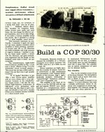
I was cleaning out some old files recently and came across the attached article from a 1966 Radio Electronics magazine, and I thought the “old timers” might get a little nostalgia kick out of it. The regulated power supply is rather unusual for a power amplifier. This was the first amplifier I ever built. I used it for at least 10 years with AR 2A speaker clones. At the time, I thought it sounded really good, I am not sure what I would think today.
Cheers,
ceulrich
Attachments
Looks like 0.9V to me ...Someone's having a laugh here, 3.6volts between the bases of the output transistors and nowhere for the current to go!
> 1966 Radio Electronics magazine
Full issue available here (7MB PDF):
https://www.americanradiohistory.co...nics/60s/1966/Radio-Electronics-1966-July.pdf
It is regulated because the 2N3055 is a 60V device, so you want to hang very close to 60V total to get all the power you paid for. Dynaco 2x60W was similar.
Full issue available here (7MB PDF):
https://www.americanradiohistory.co...nics/60s/1966/Radio-Electronics-1966-July.pdf
It is regulated because the 2N3055 is a 60V device, so you want to hang very close to 60V total to get all the power you paid for. Dynaco 2x60W was similar.
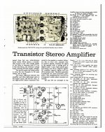
The output stage is underbiased with only two compensation diodes and a resistor, as shown in the diagram the output bias is only 0.9V, not 1.2.
Some observations:
- no bootstrap, making the VAS work harder
- emitter resistor in the VAS - good for improving frequency response
- phase lead compensation - not Miller, reducing the possibility of slew rate distortion
So while this circuit has some good features there is a strong possibility of crossover distortion. With a Vbe stabiliser, emitter resistors, and epibase NPN transistor the circuit might well perform well today.
Agree. Output transistors at 9 bucks a pop, new semiconductor technology - its not a bad effort when seen in context.
The best (commercial) vintage design Ive come across is this https://hifisonix.com/the-sa-600-amplifier/
JBL SA600.
The best (commercial) vintage design Ive come across is this https://hifisonix.com/the-sa-600-amplifier/
JBL SA600.
1)
9$U from ***1966*** !!!
Inflation calculator says:
2) very acceptable for 1966.
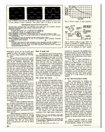
It (justly) brags about using the *first* commercially available high power Silicon power transistor.
3)
Yes, it´s underbiased, they must compensate for 4 BE junctions, so typical old style is 3 diodes (1 less than nominally needed) plus a small value resistor to get "just there", yet they use just 2.
*Maybe* they wanted to play it safe.
I'm looking at the ~$9 cost on the output transistor! Wow!
9$U from ***1966*** !!!
Inflation calculator says:
9 dollars in 1966 are equivalent to 71.45 dollars in 2018.
2) very acceptable for 1966.
It (justly) brags about using the *first* commercially available high power Silicon power transistor.
3)
oh yes it does: look at D1 and D2 1N4154 diodes.This amplifier doesn't have thermal stability resistors , neither thermal compensation Thermistors or transistor as the NAD 3020 . Does someone knows how it avoids thermal runaway?
Yes, it´s underbiased, they must compensate for 4 BE junctions, so typical old style is 3 diodes (1 less than nominally needed) plus a small value resistor to get "just there", yet they use just 2.
*Maybe* they wanted to play it safe.
This amplifier doesn't have thermal stability resistors , neither thermal compensation Thermistors or transistor as the NAD 3020 . Does someone knows how it avoids thermal runaway?
Early versions of the 2N3055 had a high intrinsic base resistance. In other words, a built-in base stopper resistor. Put a modern 3055 in the 3020 amp and they do run away. Unless you install either emitter or base resistors. Same thing with this amp. Put in emitter resistors on pain of transistor death.
$9 was not a lot for a power transistor. In today's money that would be 27 gallons of gasoline or a half day minimum-pay work.
The amp runs past class B, actually marginal class C. The idle current for 0.9V bias on two Silicon bases is nominally "zero". The crossover distortion is marginally masked by NFB, and un-mentioned because in the early days experimenters might not have the gear, might not know to look at low levels, or just kept head-in-sand posture.
Interesting that they did not bootstrap the "VAS" pull-up. That makes the large-signal output impedance a few Ohms more than it needs to be.
Why the interest? Even the published numbers are not amazing (except a lot of power for a "simple" transistor amp in 1966). You can NOT get the same baked-wafer 2N3055 that they used; the epitaxial MJ3055 was far from the same part but much simpler to make (once the technology matured), and would almost do the same work in un-critical circuits.
There are better (and worse!) amplifiers not so far in that future.
3)
oh yes it does: look at D1 and D2 1N4154 diodes.
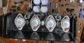
No, it doesn't. Have a close look at the pic in #5, please. Those diodes aren't even near the power devices' heat sink.
Best regards!
Agree. Output transistors at 9 bucks a pop, new semiconductor technology - its not a bad effort when seen in context.
The best (commercial) vintage design Ive come across is this https://hifisonix.com/the-sa-600-amplifier/
JBL SA600.
Glad to see here again!
Why not clone this?
")
Glad to see here again!
Why not clone this?
Thank you
Its a classic, like a JLH - some things you respect and leave alone!
- Status
- This old topic is closed. If you want to reopen this topic, contact a moderator using the "Report Post" button.
- Home
- Amplifiers
- Solid State
- A bit of amplifier nostalgia