 Split from Beyond the Ariel thread.
Hi Earl
I know this goes a long way back, this is a topic I have even broached with Lynn earlier, remember that thread re non-linear (as opposed to linear) thermal distortion in loudspeaker. You rightly pointed out that it would show up at too low frequencies. Did anything ever come up that shone some light on this, and if so, I must have missed it.
Anyhow, I have a suggestion.
Cheers, Joe
Last edited:
Hi Joe
Some time ago I tried very hard to measure nonlinearity in drivers due to thermal changes, but I was unable to find anything conclusive. Many years ago I did do some experiments that showed massive changes in a systems frequency response with time at high power. I have to now conclude that this was almost entirely due to changes in the crossover design as the components heated up and their values changed. But this later change was, of course, linear. I was never able to find significant nonlinear changes.
What is your suggestion?
Hi Joe
But this later change was, of course, linear. I was never able to find significant nonlinear changes.
What is your suggestion?
Well, it is something I mentioned to Lynn via private email quite a while back, so I wonder if he remembers it.
Basically it goes something like this: With less than 1% efficiency, most drivers has to waste 99% of the heat in the voice coil. Based on observations and comments of others, including Nick McKinney of Lambda, I realised that maybe something has been overlooked, a mechanism that would definitely be at audio frequencies, because it would involve motion of the voice coil. And also the question, where can the heat go? I decided to find out because I had a suspicion.
I took a 5.25" driver of conventional build quality, I was quite willing to sacrifice it as it was an orphan (not part of a pair). I put about 10V RMS into it at 400 Hertz. I also stuffed my ears up. Over some minutes the magnet structure, conventional ceramic type, warmed up noticeably.
This is where it gets interesting, the heat has to come from the voice coil, and it can only get into the mechanical structure one way. So this is heat convection across the gap. Guess what part of the magnet structure got warmest? No surprise, the front plate which forms part of the gap, then the ceramic doughnut and least warm was the rear plate.
Remember what Nick said way back on that thread, that in the thousands of drivers he had repaired, if the voice coil was thermally damaged, it was almost always at the front of the coil where it failed (Lambda driver were supposed to address this). Most conventional (cheap) drivers, the coil pokes out and does not have the benefit of the gap. So the middle of the voice coil runs cooler. So we have some kind of thermal time constant in the voice coil that means that the coil temperature is not uniform across its length. I suspect it is a "J" curve.
Now I was using 400 Hertz, no actual visual cone movement. But what happens when that hot voice coil starts moving as a piston in the gap when lower frequencies comes along? Will this not modulate the BL force relative to the movement? Now it is the very audio we play, so this is not ultra-low frequencies at all. The DC resistance of that part of the coil that is in the gap can be modulated by observable cone movement, and warmer parts will appear in the gap, meaning modulated lower sensitivity? Most coils are copper and we know what happens with heating up copper.
Troels Gravesen in Denmark (www.troelsgravesen.dk), I have also brought this up as a possible explanation that he prefers drivers with aluminium voice coil formers and not the usual Kapton. I suggested that the former may well give a more uniform temperature. He says that it is particularly on voices he hears this, but he may simply be into that kind of music and a different listener may hear something different?
If I might add something else. I have long been fascinated by Fletcher-Munson curves. They show that at 30 Hertz we need to hear 70dB SPL for it to become audible, the threshold. So as we descend in frequency, the audibility threshold changes. We hear higher frequencies with much lower threshold earlier than the fundamental in many cases. So if a percussion instrument centered at 30 Hertz producing many harmonics, we hear the harmonics first and then the ear/brain expects to hear the fundamental, in our case 70dB SPL. But it will take more time for that fundamental to reach the threshold. The harmonics are way ahead and creating an expectation. Any delay will affect the sound, slower? Less dynamic?
I think the two, non-uniform heating of the voice coil and that it may also be affecting the threshold of lower frequencies, that they are related. Fletcher-Munson curves has also things to say to us as to how the ear hears dynamics.
Wow! That was longer than I thought it would be. Now, have I put my head on the chopping block, or is there any sense to the above?

Cheers, Joe
PS: The driver survived, it should be around here somewhere.
Last edited:
I don't believe that this will modulate the BL. The current through the voice coil has to be the same everywhere regardless of any temperature variations along the length of the coil. Hence variations along the length will not be a factor. I was interested in time constants and the fact that the voice coil heats and cools at a rate that depends on the signal. This would modulate the BL, but, as it appears to turn out, not fast enough to be detectable. At least not by me.Now I was using 400 Hertz, no actual visual cone movement. But what happens when that hot voice coil starts moving as a piston in the gap when lower frequencies comes along? Will this not modulate the BL force relative to the movement?
If I might add something else. I have long been fascinated by Fletcher-Munson curves. They show that at 30 Hertz we need to hear 70dB SPL for it to become audible, the threshold. So as we descend in frequency, the audibility threshold changes. We hear higher frequencies with much lower threshold earlier than the fundamental in many cases. So if a percussion instrument centered at 30 Hertz producing many harmonics, we hear the harmonics first and then the ear/brain expects to hear the fundamental, in our case 70dB SPL. But it will take more time for that fundamental to reach the threshold. The harmonics are way ahead and creating an expectation. Any delay will affect the sound, slower? Less dynamic?
I am a little skeptical of this idea as well, although I may have to think about it some more. In a steady-state sense it certainly does take longer for us to recognize a LF than a HF, but in a complex tone I am not sure that the same thing would be true, but it might.
Surely the change in frequency response is more likely due to the change in voice coil impedance affecting the load on the passive crossover, rather than crossover components themselves heating up a lot and altering their values ?
That's certainly the case and I was not implying otherwise (I meant "components" to include the driver, as, of course, it is.) However, I once had a speaker where some inductors on plastic bobbins had melted, so these components CAN get hot! But the voice coil is certainly the most likely contributor.
Last edited:
...If I might add something else. I have long been fascinated by Fletcher-Munson curves. They show that at 30 Hertz we need to hear 70dB SPL for it to become audible, the threshold. So as we descend in frequency, the audibility threshold changes. We hear higher frequencies with much lower threshold earlier than the fundamental in many cases. So if a percussion instrument centered at 30 Hertz producing many harmonics, we hear the harmonics first and then the ear/brain expects to hear the fundamental, in our case 70dB SPL. But it will take more time for that fundamental to reach the threshold. The harmonics are way ahead and creating an expectation. Any delay will affect the sound, slower? Less dynamic?...
In first place thought well that's how we hear and don't know of other
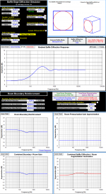
then come to think about have we ever heard such percusion sound into a real free field say hundred of feets up in the air without any boundarys at all or out in a free field with only one boundary being the ground beneath us. Think we can simulate such percusion kick into one of Jeff Bagby's spreadsheet seen attached below and see a model of how our enviroment form or boost the low end sound we have get used to over time being a kick drum for example. First spreadsheet simulate in a free field with only one boundary being the ground beneath it and being outdoor without any room pressurization gain it still adds 3dB gain at lows, second spreadsheet is indoor in a 25 sq meter room and three boundarys set plus 50% room pressurization gain, and third spreadsheet is in big indoor 300 sq meter room with three boundarys set plus 50% room pressurization gain.
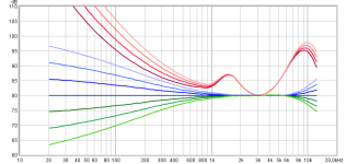
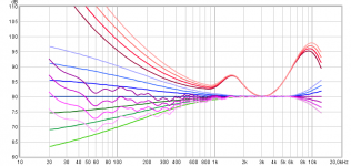
Now for reference use to below spreadsheets low end gain here is a homebrew of traced ISO226-2003 curves into REW, the dark red 80 phons curve is used being the dialed in SPL reference then the brighter the red curves go is 70/60/50 phons so we step 10dB per curve and they offset to overlay at 3kHz so to calculate correction or error curves seen below, perfect flat dark blue curve simulate the dialed in 80 phons SPL reference and the brighter the blue curves is the relative corection curves to coop for equal loudness, green curves is blue in reverse and their brighter sound signature:
Free field with only one boundary being the ground beneath it and being outdoor without any room pressurization gain:
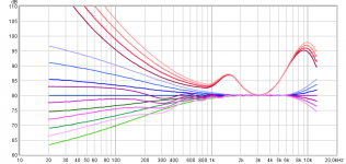
Indoor in a 25 sq meter room and three boundarys set plus 50% room pressurization gain:
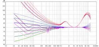
Big indoor 300 sq meter room with three boundarys set plus 50% room pressurization gain:
If this amplitude modeling is true enough to reality and timing is not ruined by non minimum phase reflections it looks we have some more or less good enough support at lowend from enviroment, especially those nasty spiking very lows (DC-like) that indoor room pressurization gain adds up.
Attachments


Last edited:
If I might add something else. I have long been fascinated by Fletcher-Munson curves. They show that at 30 Hertz we need to hear 70dB SPL for it to become audible, the threshold. So as we descend in frequency, the audibility threshold changes. We hear higher frequencies with much lower threshold earlier than the fundamental in many cases. So if a percussion instrument centered at 30 Hertz producing many harmonics, we hear the harmonics first and then the ear/brain expects to hear the fundamental, in our case 70dB SPL. But it will take more time for that fundamental to reach the threshold. The harmonics are way ahead and creating an expectation. Any delay will affect the sound, slower? Less dynamic?
The flaw in this dawned on me. This effect always happens to us, when we listen live or when we listen to a reproduction. So if the playback level is the same as the original then our ears will respond exactly the same in both cases. If the playback is at a lower level then it is well know that we might want to add some bass. But it is also true that there is a level where the playback just seems to click into place and sound right. That's probably the level that it was mixed at.
The flaw in this dawned on me. This effect always happens to us, when we listen live or when we listen to a reproduction. So if the playback level is the same as the original then our ears will respond exactly the same in both cases. If the playback is at a lower level then it is well know that we might want to add some bass. But it is also true that there is a level where the playback just seems to click into place and sound right. That's probably the level that it was mixed at.
Well said. The playback we want to replicate is the mastering environment, when the final balancing and sign-off approval by the musicians and producers is made. The loudspeakers in a mastering room are typically large floor-standing loudspeakers (not soffit-mounted) in a quasi-domestic environment, so the floor bounce and LF room gain become part of the mastering environment. An expectation of a domestic environment is already "baked in" to the balance of the final mix.
The floor bounce and LF room gain are annoying things we want to get rid of when measuring loudspeakers (so we can separate the room from the loudspeaker), but the target environment is domestic, not a concert hall, not a movie theater, and not sound reinforcement.
This has to be kept in mind when considering the overall sound of the loudspeaker from 300 Hz on down. It's not going to be 20 feet up in the air; it's going to sit on the floor, or an a stand. The wall behind and the nearest side-wall are probably going to be 1 to 2 meters away at the furthest, and maybe closer, depending on room size.
Hi Joe
Some time ago I tried very hard to measure nonlinearity in drivers due to thermal changes, but I was unable to find anything conclusive.
It has to be something that changes the current through the voice coil, even if it is crossover related.
Many years ago I did do some experiments that showed massive changes in a systems frequency response with time at high power. I have to now conclude that this was almost entirely due to changes in the crossover design as the components heated up and their values changed.
That is interesting. But again I believe the key here again is the current, how does it affect the final current through the voice coil. Not the voltage across the voice coil, the driver does not respond to that, although on the surface it seems to.
But this later change was, of course, linear. I was never able to find significant nonlinear changes.
What is your suggestion?
Where do I start? I equalise the current of the amplifier. This are done by parallel components. Then I only use series components to do the crossover filtering. The parallel EQ must be seen by the amplifier directly. Parallel = current EQ and series = frequency filtering. That does several things, since the impedance can only go up with added series impedance, the EQ of the current becomes easier (i know in practice that is a challenge). The current phase angle goes flat, makes it difficult for the amplifier to produce reactive current. The amplifier has no control of the current, only the voltage. Yet what we hear is the current that ultimately arrives and goes through the voice coil. So I go into 'current management' mode and look for ways, mechanism and techniques to do just that. So what I am saying here is just the tip of the iceberg. But I am hearing real pay-offs doing it this way. In a good system, the speakers does a disappearing act. There is also a perceived lower level of hash, a kind of noise floor. I spoke to Dan and there is a good reason to see that currents are cycling and smearing things out. The amplifier current is modified by the speaker, then it reacts, the speaker reacts to this changed current and the cycle has started, only to be reduced by change in content. What is remarkable is just how easy it is to hear this. But to do it is also quite a challenge.
They used to say 'follow the money' and in this case I say 'follow the current' in the sense, what is it really doing? Not just the driver, what does crossover do to the current? If we hear an anomaly that can be changed, the change you hear is a change to current. Mind you, to come across to this fundamental way of looking at things did not come easily, you have to give us things you previously treasured as important.
So, there you are. I don't say the voltage model should be entirely thrown out (I use computer modelling based on it and will continue to), but only say that it will not give us the complete picture.
Last edited:
Where do I start? I equalise the current of the amplifier. This are done by parallel components. Then I only use series components to do the crossover filtering. The parallel EQ must be seen by the amplifier directly. Parallel = current EQ and series = frequency filtering. That does several things, since the impedance can only go up with added series impedance, the EQ of the current becomes easier (i know in practice that is a challenge). The current phase angle goes flat, makes it difficult for the amplifier to produce reactive current. The amplifier has no control of the current, only the voltage. Yet what we hear is the current that ultimately arrives and goes through the voice coil. So I go into 'current management' mode and look for ways, mechanism and techniques to do just that. So what I am saying here is just the tip of the iceberg. But I am hearing real pay-offs doing it this way. In a good system, the speakers does a disappearing act. There is also a perceived lower level of hash, a kind of noise floor. I spoke to Dan and there is a good reason to see that currents are cycling and smearing things out. The amplifier current is modified by the speaker, then it reacts, the speaker reacts to this changed current and the cycle has started, only to be reduced by change in content. What is remarkable is just how easy it is to hear this. But to do it is also quite a challenge.
I don't quite follow you here. Basically, in a linear system, and audio is basically a linear system, or it would be unlistenable, the current and voltage are intimately related to each other - if I know the impedance structure of the system then I can measure either one and get the same answer.
I don't quite follow you here. Basically, in a linear system, and audio is basically a linear system, or it would be unlistenable, the current and voltage are intimately related to each other - if I know the impedance structure of the system then I can measure either one and get the same answer.
II hear you and get that, but I still maintain that we tend to think voltage and not get the complete picture. Thinking voltage is an easy language, I find that current it not. Try explain current drive to the average guy, it is so counter-intuitive. I am not a proposing current drive though. Some get me confused about that. I use amplifiers that have typically 5 Ohm output impedance, because I make my own.
Take a manufacturers driver, where you have two versions, 4 Ohm and 8 Ohm. I am thinking of an actual 6" driver from a premium source. The voltage sensitivity is 89dB for 8 Ohm and 92dB for 4 Ohm. The voltage is the same, 2.83V RMS. The extra 3dB is entirely down to current, not voltage. Change current by 2:1 and it will be 3dB.
F=Bli where F is the final dB-SPL product.
I have tested this over and over again, the dB-SPL of the driver is always proportional to current and never the voltage. The above example proves it because the voltage did not change, only the current. I can give numerous examples where I have physically tested this as well as in SoundEasy modelling.
And isn't that what we ought to expect, when drivers are current devices. Yes, there is voltage there and yes, you need to have both to see the complete picture, such as calculating dissipated power.
Also, I put this fundamental thought to a physicist with a track record in he loudspeaker industry (I could name drop here) and quite in depth, more than I could cover here. One of the ideas is the back-EMF of the driver is an impedance since it impedes current. An impedance is always about the current and so is the impedance plot. Since back-EMF (motional, inductive, microphonic) impedes current, it is an impedance. And it can be measured at any frequency, the top of the impedance minus Re is the back-EMF impedance at that frequency in Ohm. It is a voltage source opposing and modifying the current of the amplifier. Only Re limits the back-EMF, which is just as well. The amplifier has no control over the current. It can only control the voltage.The voltage across Re times the current (less and impeded by he back-EMF impedance) is what gets dissipated in the voice coil and less that 1% gets converted to F or dB-SPL. The numbers that has come up supports this. The voltage across the Re part of the impedance is not the same voltage as that of the voltage source, the amplifier.
One thing is interesting though, if you EQ the current, so that the amplifier supplies the same current at all frequencies, then you have effectively cancelled out the output impedance of the amplifier. It is still there, but there will be no deviation in FR. This can be done to near perfection with sealed boxes and more difficult with vented boxes. It also makes the crossover not need to see a zero source impedance, so both box alignment and crossover behaves the same.
So that is incredibly practical too. Especially with the kind of amplifiers I do, 5 Ohm typically. The box alignment does not need to see zero Ohm.
Whew! That was more than I intended to type...
I don't quite follow you here.
You're not alone. Joe, you make very ordinary principles of EE sound like some kind of mystical gibberish.
Last edited:
You're not alone. Joe, you make very ordinary principles of EE sound like some kind of mystical gibberish.
Here we go again. Scott, no comment. What I stated was confirmed by somebody with more science degrees and doctorates than I can count. F=BLi is not gibberish. It might be to you, but that is not for me to say. Constructive criticism is welcome, ad hominem statements are not.
What I stated was confirmed by somebody with more science degrees and doctorates than I can count. F=BLi is not gibberish.
It's not something that anyone skilled in the art does not know, why do you keep saying the opposite? We all know this stuff there is no contradiction to general knowledge here. If there was any personal attack in my comment I missed it.
Joe, I remember discussing this with you once. The idea of conjugating a speaker impedance to make it appear resistive (and the opportunities that follow this), a concept that those of us who build both amps and speakers have likely realised independently. Is there something more than this that you are suggesting?
Joe, I remember discussing this with you once. The idea of conjugating a speaker impedance to make it appear resistive (and the opportunities that follow this), a concept that those of us who build both amps and speakers have likely realised independently. Is there something more than this that you are suggesting?
Well, that depends on the climate, probably not here.
I am a great admirer of your Elsinore speaker, Joe.
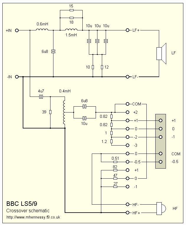
I do think your simple assertion that flat impedance is a good thing was unjustly maligned by the minority hooligan crowd at DIY. The BBC designed the 8" plus 1" LS5/9 for an active filter, but found the passive filter was so good that they didn't need it. It was a very special filter IMO. Used impedance conjugation.
Not hard to do something similar:
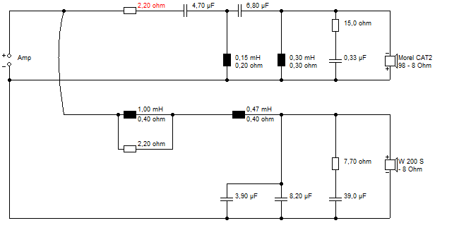
Look at THAT! Nice, eh?

It works quite nicely in closed box with significant amplifier output impedance of course. But not perfectly. A voltage amplifier does a much better job of separating the two legs of the filters. I haven't quite figured it out, but if the amp is above zero ohms output impedance, the drivers interact.
I do think your simple assertion that flat impedance is a good thing was unjustly maligned by the minority hooligan crowd at DIY. The BBC designed the 8" plus 1" LS5/9 for an active filter, but found the passive filter was so good that they didn't need it. It was a very special filter IMO. Used impedance conjugation.
Not hard to do something similar:
Look at THAT! Nice, eh?
It works quite nicely in closed box with significant amplifier output impedance of course. But not perfectly. A voltage amplifier does a much better job of separating the two legs of the filters. I haven't quite figured it out, but if the amp is above zero ohms output impedance, the drivers interact.
I am a great admirer of your Elsinore speaker, Joe.
I do think your simple assertion that flat impedance is a good thing was unjustly maligned...
Thanks, but this is not just about flat impedance, I always felt that the current phase angle of the amplifier was the key to perhaps unlocking something that was maybe a little less obvious. Then something Neville Thiele did probably first 60 years ago, struck me. He plotted the impedance using current, constant current. Under those conditions, the impedance of he driver is plotted as proportional to the voltage across the driver terminals. There cannot be any reactive current, no matter how 'reactive' we think the speaker is. He used a 1000 Ohm resistor to create constant current. Series resistance. The other thing it made me raslise was that the Re DC resistance of the voice coil, does not change, which means that everything that measures higher in the impedance plot, is actually back-EMF, because it is clear measured by Thiele as a voltage, and hence we have it, the back-EMF is a voltage source, but it is also an impedance, because it opposes the current of the amplifier. It can be measured in Ohm.
Now the pieces seemed to start to fit. That back-EMF is an impedance and a voltage source. So at any frequency we can measure the back EMF impedance by simply subtracting the Re that does not change we frequency.
Make the amplifier supply the same current at all frequencies, it is as simple as that. Only good can come from it.
I have a 6.5" driver, Re = 6 Ohm, at 3400 Hertz, the impedance is 18 Ohm. Thus the back-EMF impedance is 12 Ohm at that frequency. That impedance is not reactive under Thiele's conditions. It becomes reactive when we use voltage to drive it.
Now this is all well and done and I think should be obvious to us. But only the current that gets to the Re part of the impedance, that current also creates a voltage (again, think of Thiele's constant current, where the impedance become proportional to the voltage), BUT this is the important one and very different that the voltage that comes from the amplifier, and current phase shift and all. It is also in the back-EMF impedance where a cone resonance or anything bad will show up. The back-EMF impedance is not stable at all, but the Re is. But what we listen to is what happens at Re, the voltage there being different from the amplifier is what matters, the voltage and current, but since it is the current that really matters and the voltage is only an indicator of what has gone wrong, it is the current we end up listening to.
So simply, if we make the impedance flat, the current phase angle of the amplifier flat (which is what happens when we make the impedance flat) and the current from the amplifier now become difficult for the load to create reactive current. And since it is the speaker hat causes the amplifier to create reactive current, which then becomes cyclic and ongoing, but if the amplifier won't play along, then the cycle is broken. You will still have the back-EMF impedance changing the current, but prevent the amplifier from chasing its own tail, that gets nipped in the butt.
So it isn't so much about the flat impedance, it is really about managing the current of the amplifier, stop it from 'singing along' if you know what I mean.
Above is just an attempt to encapsulate the topic.
Cheers, Joe
Last edited:
Just for levity: I am reminded when Dr Niels Bohr had a visitor and he was about to open the front door when he noticed the visitor looking at the horseshoe above the door. The visitor thought, could the famous professor Bohr really be superstitious? Of course the horseshoe had been there for a hundred years. Bohr, quickly sizing up the situation remarked: "I have been told they work even if you don't believe in them."
Back EMF is due to motion of the driver itself, the impedance rise with frequency is due to inductance. While there can be reactive component as with inductors, I would not consider it back EMF. Reducing the inductance of the voice coil certainly help reduce reactive issues.
Current phase issue is one I had mentioned years ago, but it would be interesting how in practice we can control this through the amplifier. Also consider that the mic during the recording process already starts to introduce phase shift, additionally, the limited electronics bandwidth also introduces phase shift during playback. So trying to reduce phase shift throughout or compensate for such systemwide digitally is a major effort which I think would prove worthy.
Current phase issue is one I had mentioned years ago, but it would be interesting how in practice we can control this through the amplifier. Also consider that the mic during the recording process already starts to introduce phase shift, additionally, the limited electronics bandwidth also introduces phase shift during playback. So trying to reduce phase shift throughout or compensate for such systemwide digitally is a major effort which I think would prove worthy.
- Status
- This old topic is closed. If you want to reopen this topic, contact a moderator using the "Report Post" button.
- Home
- Amplifiers
- Solid State
- Back-EMF and flat impedance