Hi, I designed a PCB for a KX-amplifier with SMD components. The amplifier oscillates at about 16 MHz, probably due to oscillations, the bias is still growing. The amplitude of the oscillations is max. 1V, most often around 0.6 V. I used BC847 / BC857 transistors everything else according to hifisonix. When I connect Q3 / Q4 / Q10 / Q11 with my fingers, the oscillation is removed and the bias decreases and no longer increases. I have no idea where I can damping the oscillations. Removal of C5 / C1 did not help. Other components are measured and OK. Now i buy original PCB for THT devices and now waiting for dolivery, I hope the original pcb won't oscillate
Perhaps, something which can be useful for other builders of this amp.
At first run of the amplifier (after individual trials of each boards with lab power supply), I got a little bzzz with the two channels inputs connected (no noise at all with inputs disconnected or shorted). The noise was small (I can only hear it by putting my head close to the loudspeaker).
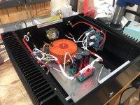
After dressing of the main cables to the boards: no noise at all (2705 pic)
I have also pics of the 1k, 10k and 50k square wave
At first run of the amplifier (after individual trials of each boards with lab power supply), I got a little bzzz with the two channels inputs connected (no noise at all with inputs disconnected or shorted). The noise was small (I can only hear it by putting my head close to the loudspeaker).
After dressing of the main cables to the boards: no noise at all (2705 pic)
I have also pics of the 1k, 10k and 50k square wave
Attachments
")
Thanks
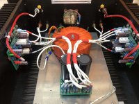
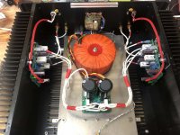
Some pics
Another view of the amplifier
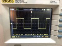
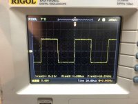
Square wave 8V 1kHz
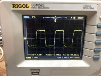
Square wave 8V 10 kHz
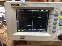
Square wave 8V 50khz
Square wave 8V 30hz
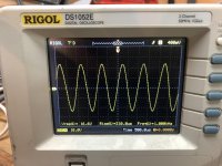
Sine wave just before clipping 16,6V rms
All measurements into 8 ohm dummy load
I made a sub plate (Alu 4mn) to avoid drilling main chassis for components
The plate is ready for ripple eater
I use a remote control switch
Some pics
Another view of the amplifier
Square wave 8V 1kHz
Square wave 8V 10 kHz
Square wave 8V 50khz
Square wave 8V 30hz
Sine wave just before clipping 16,6V rms
All measurements into 8 ohm dummy load
I made a sub plate (Alu 4mn) to avoid drilling main chassis for components
The plate is ready for ripple eater
I use a remote control switch
Attachments
Very nice Bouli! Thanks for the measurements. Can you do a BODE plot to illustrate the frequency response of the amplifier? Or set sinewave output to 2.83V RMS (8VPP with 8 ohm load for 1 watt) and find at what frequencies the output is 3 dB down (2V RMS or 5.6V PP)?
Thanks,
Anand.
Thanks,
Anand.
@Anand
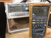
It's easy with Fluke db features. So the process was:
amplifier on dummy load 8ohm
1hkz sine wave input to have a few volt on load
Set the fluke on db
Set reference value (db rel)--->0 db rel (at 1 kHz)
Don't move level on generator and increase frequency up to -3db on load
You can see the pic: -3db at 202khz
@Bonsai
It's a Chinese chassis
You can find it on Aliexpress (search with amplifier, heatsinks, enclosure)
Attachments
@Anand
It's easy with Fluke db features. So the process was:
amplifier on dummy load 8ohm
1hkz sine wave input to have a few volt on load
Set the fluke on db
Set reference value (db rel)--->0 db rel (at 1 kHz)
Don't move level on generator and increase frequency up to -3db on load
You can see the pic: -3db at 202khz
@Bonsai
It's a Chinese chassis
You can find it on Aliexpress (search with amplifier, heatsinks, enclosure)
To be more accurate, you must inspect generator level output during test.
Not all generators are stable level output when frequency vary.
To be more accurate, you must inspect generator level output during test.
Not all generators are stable level output when frequency vary.
True and it depends on the load. But most generators should handle the bandwidth of this amp I hope. 1MHZ would be decent.
Best to have a second RMS multimeter attached to the generator output to verify the voltage hasn’t dropped.
Which is why I use a scope with BODE plot capabilities and track input and output waveforms.
Best,
Anand.
Hi, I designed a PCB for a KX-amplifier with SMD components. The amplifier oscillates at about 16 MHz, probably due to oscillations, the bias is still growing. The amplitude of the oscillations is max. 1V, most often around 0.6 V. I used BC847 / BC857 transistors everything else according to hifisonix. When I connect Q3 / Q4 / Q10 / Q11 with my fingers, the oscillation is removed and the bias decreases and no longer increases. I have no idea where I can damping the oscillations. Removal of C5 / C1 did not help. Other components are measured and OK. Now i buy original PCB for THT devices and now waiting for dolivery, I hope the original pcb won't oscillate
I left SMD, and use original PCB from jims audio. Small transistors are BC546B BC556B. Amplifier stil oscilating, i must solder capacitors about 300pF on power transistors (B-C) shown on PCB as SMD caps = oscilation damped, but bias current is stil high, for low bias setting is current higher than 400mA per transistor pair. then I edit R8 = 2.2k and R18 = 47k, now oscilattion is damped and bias current with these values is 200mA per transistor pair. Temperature stability is OK. Are these changes OK, what can i expect?
Hello everyone.
Again my hiatus was killed and i took some time to test. this time RE worked flawlessly, no AC on output.
I even had sound coming, only 0.2V DC on speaker terminals.
then....
when I was setting trimpot, cheap alligator clip got slipped and shorted d4 and r36.
Now I have 15v on D4, 2VDC on SPK term, and other stuff...
I think I'll try to get hot air station to replace Q12-15.
maybe you'd have other ideas?
Hi all, I’ve finally gotten around to start the FX build. I love how the boards are labeled with with both the reference designations and values. Makes it much easier to assemble correctly.
Once comment on the BOM, the Qty of fuse holder per board should be two, vs 1 as the part number specified come as singles not pairs.
I also have a question about the coil, L1. I made the coils from 12 turns of 17 AWG (0.045”) wire on a 0.375” former. The coil ends up with an inside diameter of 0.39 since it tends to spring back a little after winding. I tried to measure the value and it measures 0.9 to 1 uH. I took one turn off and it measured the same. So my measurements must not be that accurate. How sensitive is the amplifier to the value of this coil? Is it OK to just go with the 12 turn coil, or do I really need to accurately get it to between 0.6 and 0.7 uH?
Thanks. Can't wait to hear how they sound.
After playing around a little bit with over-biasing various DIY amps, and playing around, I found it was time to try something that is properly designed, and this amp caught my eye with a lot of features I like, and also with some references to the JLH class A, which is my favorite at the moment ('sublimed PNP JLH' with floating ground).
The SX would probably be enough for my needs, the JLH is at 99% of the time, but I saw there are some prolems sourcing components, and the better distortion figures of the kx also seems nice.. Compared to the JLH I would like some more control in the bass than the JLH offers, and if possible a little bit more 'resolution/detail', but keep the 'smooth' sound, I'm hoping the kx will deliver this.
I ordered the ripple eater PCB too, not sure what I will use. I will try to use some recycled parts for the PSU and heat sinks to save money. Probably it will be a 'prototype build' first, just to listen to it, and built into a chassis if I like how it sounds. Also debating with my self what bias level to aim for. The low bias is most likely enough for my listening levels.
It will take a couple of weeks to get the PCB's from China, so I will start looking at the BOM in the meantime. Anything I should know or think about before ordering components?
- Home
- Amplifiers
- Solid State
- Hifisonix kx-Amplifier